Design and hydraulic performance test of a jet-impingement sprinkler at low pressure
-
摘要:
为分散喷头主射流,提高喷头的喷洒均匀度,使喷头适用于农业低压喷灌,该研究结合射流与撞击流提出了一种射流撞击式旋转喷头。首先对比了射流撞击喷头与射流不撞击喷头的水力性能,通过正交试验分析了各结构参数值对射程和组合均匀系数的影响,得到副喷嘴结构优化参数,最后将优化后的射流撞击喷头与改进前的传统15PY2喷头进行水力性能及水滴粒径分布对比。研究结果表明,射流撞击使射程末端水量高点降低,同时射程得到提升,射程平均提升4.39%,在相同压力及组合间距下覆盖范围更大。影响喷头工作性能的结构参数依次为副喷管长度、副喷嘴进口锥角、副喷管内径、副喷嘴仰角,而副喷嘴仰角对射程与组合均匀系数影响最大,15型射流撞击喷头最佳结构参数组合为:副喷管长度20 mm、副喷嘴进口锥角55°、副喷管内径6 mm、副喷嘴仰角33°。射流撞击喷头在压力150~300 kPa下组合均匀系数和综合评分均高过传统15PY2喷头,组合均匀系数平均提升4.84%,综合性能平均提升4%,证明了射流撞击应用于旋转式喷头具有优势。在射程前中段,150和250 kPa下射流撞击喷头水滴直径更大;在射程后段,150 kPa下射流撞击喷头水滴直径更大,但在250 kPa下水滴直径更小。研究所得到的喷头结构及结论可为后续研究射流撞击对水力性能的影响提供参考。
Abstract:An asymmetric impinging jet collision mode is adopted to design the jet impingement sprinkler. By using the secondary jet to collide with the main jet, the movement and fragmentation mode of the main jet are changed to optimize the dispersion effect of the jet. The main body structure of the sprinkler is similar to that of a traditional impact sprinkler to meet the wetted radius requirements. The focus of the study is on the structure of the secondary nozzle, including the inner diameter of the secondary spray tube, the elevation angle of the secondary nozzle, the length of the secondary spray tube, and the inlet cone angle of the secondary nozzle. The sprinkler is made of aluminum alloy material and designed with a segmented structure plug-in design to avoid changes in the jet direction caused by threaded connections. The wetted radius and Christiansen's uniformity coefficient are selected as evaluation indicators. The wetted radius is calculated using interpolation algorithms, and the Christiansen's uniformity coefficient is calculated by using MATLAB program and a interpolation mathematical model to calculate the radial water application rate distribution for the square layout scheme. The experiment is conducted in a windless experimental hall, and the influence of various geometric parameters of the secondary nozzle on the water application rate distribution is evaluated through comprehensive evaluation of the wetted radius and Christiansen's uniformity coefficient using the CRITIC weighting method.According to the experiment, the coefficient of variation of flow rate for the nine different combinations of structures under different pressures is less than 2%. It can be concluded that the four structural parameters changed in this study do not affect the flow rate. By analyzing the average flow rate of the nine combinations, it is found that the flow rate is proportional to the pressure, and the flow rate at each test pressure is greater than 0.08 m3/h, which means that the wetted radius of the sprinkler is the farthest distance from the centerline of the sprinkler to the point where the water application rate is 0.26 mm/h. By comprehensive scoring, the optimal structural combination for the full pressure range of 150~300 kPa is secondary spray tube length of 20 mm, secondary nozzle inlet cone angle of 55°, inner diameter of secondary spray tube of 6 mm, and secondary nozzle elevation angle of 33°. A comparison experiment of the water hydraulic performance between the jet impinging sprinkler and the non-impinging sprinkler shows that the jet impinging sprinkler has a longer wetted radius and a slightly different water application rate distribution. Hydraulic performance tests were conducted on the optimal structure and the traditional 15PY2 sprinkler. It was observed that, under low pressure, the wetted radius of the jet impinging sprinkler decreased, while the Christiansen’s uniformity coefficient increased. Under medium pressure, the wetted radius increased, and uniformity improved. Moreover, the comprehensive performance of the jet impinging sprinkler was found to be superior to that of the traditional 15PY2 sprinkler under a full pressure range of 150 to 300 kPa. Finally, a comparison was conducted to analyze the droplet size distributions of the traditional 15PY2 sprinkler and the jet impingement sprinkler in the anterior middle and posterior sections. The results show that the jet impingement sprinkler produces larger droplet diameters at 150 and 250 kPa in the anterior middle section of the wetted radius. However, in the posterior section, it only exhibits larger droplet diameters at 150 kPa. At 250 kPa, the droplet diameters are smaller. The obtained structure and conclusions of the study provide a reference for future research on the hydraulic performance affected by jet impingement.
-
Keywords:
- irrigation /
- nozzle /
- hydraulic performance /
- jet impingement /
- orthogonal test
-
0. 引 言
气候变化和人口增长的综合影响使水和能源的需求及成本呈指数级增长[1],农业节水已成为缓解中国水资源短缺的必然选择与根本出路[2]。喷灌是农业节水中一种有效的灌溉方式,喷头被视为喷灌系统中确保节水的关键部件[3-5]。为了达到节能节水的目的,降低喷头工作压力的同时保证均匀性是当前喷头研究的重点。
在固定式旋转喷灌系统中,当喷头的工作水压力较低时,存在喷头附近和射程中段的水量较少,而射流末端水量集中的问题,为了改善这种情况,已有研究者采用多种方法来分散水射流。由美国Nelson公司生产的R2000、R33等系列喷头,采用环形散水盘外圈分布散水齿的结构,射流冲击散水齿达到分散射流的目的[6],李红等[7]采用正交试验方法研究了散水齿的结构参数对旋转式喷头 R33 水力性能的影响,确定了散水齿的最佳结构参数,并建立了散水齿影响区域最短射程的计算方法。范兴科等[8]在摇臂式全园喷洒喷头的基础上进行了结构改造,增加了喷洒雾化度调节机构,该机构在喷嘴下方装置了有利于射流水雾化的散水撞针,以增强射流的破碎效果,从而提高喷头的喷洒雾化度。JIANG等[9]设计了不同类型的喷嘴,并在低压条件下使用散水针进行了试验,通过对初始射流破碎长度、分散角、喷嘴尺寸和工作压力等参数的曲线拟合,建立了具有分散装置的喷头的射程公式。PAN等[10-11]通过试验与数值模拟相结合的方法,分别研究了散水针与散水齿对射流破碎和水力性能的影响,结果表明两种射流分散方法增强了射流破碎的同时造成了较高的能量及喷头射程损失。
射流撞击作为一种常见的流体力学现象,经常出现在气体和液体的注入、混合和分离等过程中。射流撞击现象十分复杂,受到多种因素的影响,如射流初速度、射流直径、射流撞击角度、射流撞击距离等[12-14]。射流撞击常用于导弹与火箭推进剂雾化、水煤浆气化、药物吸入治疗、固体颗粒制备等很多领域,近年也将射流撞击应用于植保喷头[15-16],设计出的喷头具有雾滴粒径均匀性较好、雾滴谱较窄、调压范围宽和抗飘性较强的特点。而现有灌溉喷头射流分散方法(如散水齿、散水针等)多以液-固撞击为主,射流撞击固体造成了部分射流动量减小甚至反向撞击前部射流,最终导致较高的射程损失,而液-液射流撞击不会造成动量损失,当两股射流的撞击角小于90°时,合成动量会比任一射流的动量更大,这种射流撞击方式不仅有助于射流的分散,还可能对射程产生促进作用,因此考虑将液-液射流撞击应用在喷灌领域。
鉴于此,本文基于射流撞击方法研制一种通过主副射流相撞击的旋转喷头,采用正交试验确定喷头副喷嘴主体结构的最佳结构参数,并通过与射流不撞击喷头对比得到射流的撞击对于水力性能的影响。
1. 射流撞击式喷头设计
1.1 射流撞击原理
传统对称射流撞击的雾化机理是两个射流速度和射流直径相等的圆柱形液体相互碰撞。这种撞击产生了一个垂直于两股射流动量矢量的扁平液膜。液膜上的不稳定性会促进破碎。液膜分解成圆柱形的液带,然后液带分解成液滴。破碎主要是由空气动力和惯性力引起的,并受到表面张力的影响[17-18]。在灌溉喷头设计中,除追求更高的喷洒均匀性外,射程也是重要的性能参数,对称式同径的射流撞击模式虽然雾化效果出众,但会造成射程显著降低,因此本研究设计的喷头采用非对称异径射流撞击模式,喷头有主副两个喷嘴,其中主喷嘴孔径大于副喷嘴孔径,通过副射流撞击主射流,以改变主射流的运动及破碎模式,达到优化射流分散效果进而提高水力性能的目的。根据射流撞击原理设计的射流撞击喷头工作原理如图1所示。
![]() 图 1 射流撞击喷头工作原理示意图1.主射流 2.副射流 3.射流撞击点 4液膜 5液滴Figure 1. Schematic diagram of working principle of jet impingement sprinkler1. Primary jet 2. Secondary jet 3. Jet impingement point 4. Liquid sheet 5.Droplets
图 1 射流撞击喷头工作原理示意图1.主射流 2.副射流 3.射流撞击点 4液膜 5液滴Figure 1. Schematic diagram of working principle of jet impingement sprinkler1. Primary jet 2. Secondary jet 3. Jet impingement point 4. Liquid sheet 5.Droplets1.2 喷头结构设计
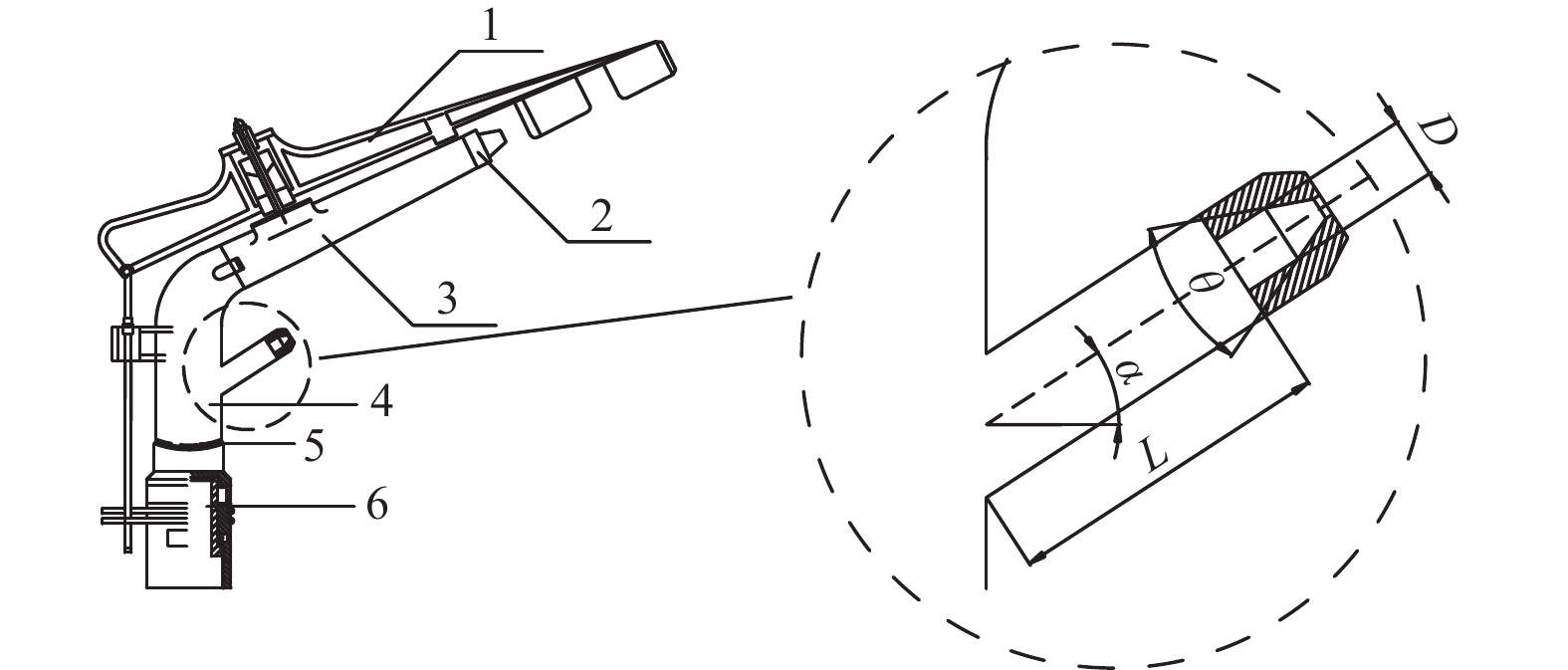
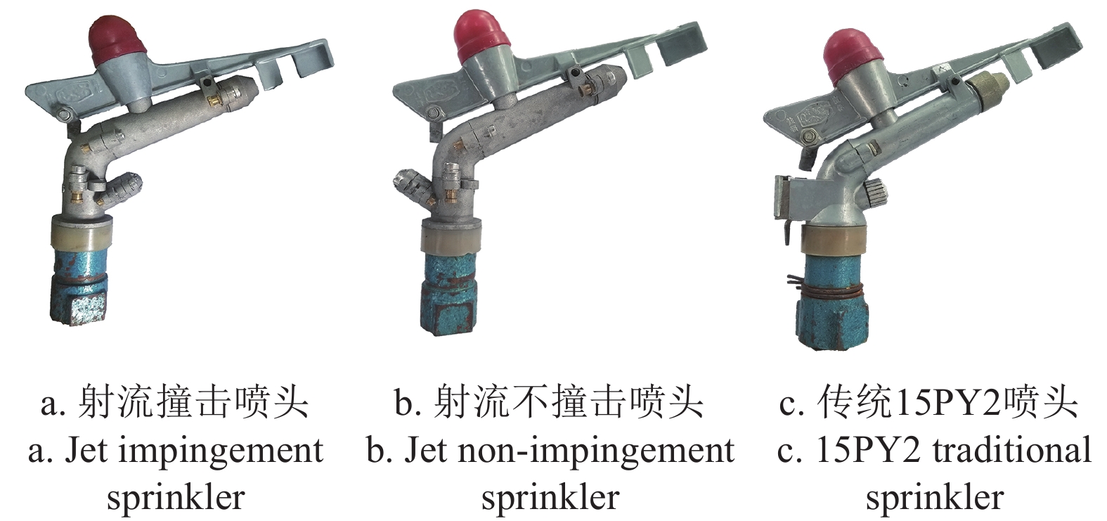
射流撞击喷头的结构尺寸及主副喷嘴相对位置及角度变化会对射流撞击距离、射流撞击角度等产生影响,进而影响喷头水力性能。为了确保射流撞击喷头满足规定的射程要求,喷头主喷管结构与传统15PY2保持一致,为实现主副射流撞击,适当增加主副喷管之间的距离。本研究将副喷嘴结构作为研究重点,副喷嘴主体结构参数包括副喷管内径、副喷嘴仰角、副喷管长度、副喷嘴进口锥角,喷头结构如图2所示。试验加工喷头采用铝合金材质以保证喷头强度要求,为了便于试验更换及互配,采用分段的结构设计,将下喷体分为上下两部分,将副喷嘴分为副喷管与副喷嘴两部分,并将本研究所有结构加工成零件,由于螺纹连接的喷嘴在装配过程中射流方向会随安装时有一定旋转,可能导致主副射流无法形成撞击,为保证主副射流方向保持在同一平面,喷嘴部分未采用传统的螺纹连接结构,改用插接内部安装止水垫片,并在两侧设限位孔安装螺丝限位,通过面于面对齐保证喷嘴安装时不会改变射流轴线方向,本次试验样机结构主体参数为进水口公称直径15 mm,主喷嘴仰角26°,根据规范GB/T 22999−2008《旋转式喷头》可知,15 mm进水口公称直径双喷嘴喷头选取主喷嘴4~6 mm,副喷嘴取2.5~3.0 mm,本研究选取主喷嘴孔径4 mm,副喷嘴孔径3 mm进行试验。将主喷体反装,使副喷嘴射流与主喷嘴射流在相反的方向上得到射流不撞击喷头,用于和射流撞击喷头进行对比试验,本次试验所用喷头结构如图3所示。
![]() 图 2 喷头主体结构1.摇臂 2.主喷嘴 3.主喷管 4.副喷嘴5.下喷体 6.下轴承Figure 2. Main structure of sprinkler1. Rocker arm 2. Primary nozzle 3. Primary spray tube 4. Secondary nozzle 5. Lower spray body 6.Lower bearing 注: α 为副喷嘴仰角,(°); θ 为副喷嘴进口锥角,(°); D 为副喷管内径,mm; L 为副喷管长度,mmNote: α is secondary nozzle elevation angle, (°); θ is secondary nozzle inlet cone angle, (°); D is inner diameter of secondary spray tube, mm; L is secondary spray tube length, mm
图 2 喷头主体结构1.摇臂 2.主喷嘴 3.主喷管 4.副喷嘴5.下喷体 6.下轴承Figure 2. Main structure of sprinkler1. Rocker arm 2. Primary nozzle 3. Primary spray tube 4. Secondary nozzle 5. Lower spray body 6.Lower bearing 注: α 为副喷嘴仰角,(°); θ 为副喷嘴进口锥角,(°); D 为副喷管内径,mm; L 为副喷管长度,mmNote: α is secondary nozzle elevation angle, (°); θ is secondary nozzle inlet cone angle, (°); D is inner diameter of secondary spray tube, mm; L is secondary spray tube length, mm1.3 试验设计与方法
1.3.1 试验方案
选取副喷嘴仰角α、副喷管内径D、副喷管长度L、副喷嘴进口锥角θ为正交试验因素。副喷嘴仰角选择区间27°~33°,可以实现射流撞击且不会对摇臂运动产生影响;副喷管内径根据传统15PY2副喷嘴入口直径为6 mm,选择4~6 mm;传统15PY2副喷管长度较小,仅为5~6 mm,根据DOMBROWSKI 等[19]的研究,射流撞击的工作液体需要经过较长的管道以获得充分发展的速度剖面,因此本研究的副喷管选择了10~30 mm的较长范围区间;副喷嘴进口锥角选择较为常用的35°~55°进行研究[20]。选择因素水平如表1所示。选用L9(34)正交表,正交试验方案如表2所示,并将最终优化结果与传统15PY2喷头对比。
表 1 因素水平表Table 1. Factor and level水平
Level因素Factors 副喷嘴仰角
Secondary nozzle elevation angle
α/(°)副喷管内径
Inner diameter of secondary spray tube
D/mm副喷管长度
Secondary spray tube length
L/mm副喷嘴进口锥角
Secondary nozzle inlet cone angle
θ/(°)1 27 4 10 35 2 30 6 20 45 3 33 8 30 55 表 2 试验方案Table 2. Test scheme试验号
Test No.α/(°) D/mm L/mm θ/(°) 1 27 4 10 35 2 27 6 20 45 3 27 8 30 55 4 30 4 20 55 5 30 6 30 35 6 30 8 10 45 7 33 4 30 45 8 33 6 10 55 9 33 8 20 35 1.3.2 试验装置及设计
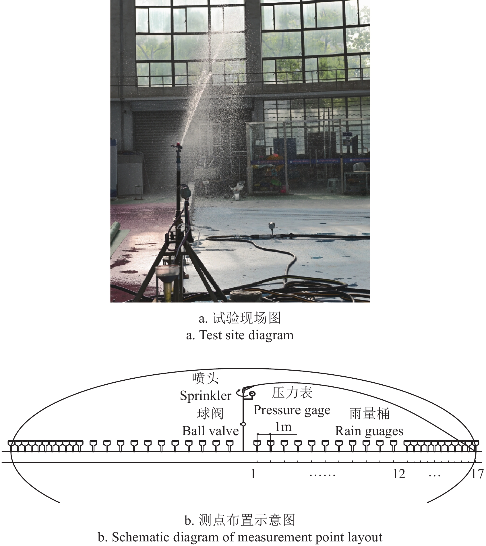
样机试验在直径为44 m的无风喷灌实验大厅进行。喷头安装高度为1.4 m,在工作压力分别为150、200、250和300 kPa的工况下做全圆喷洒。由于喷灌大厅内无风,因此可以用两条射线上的数据平均代替圆周内的各条射线。如图4所示,在这条射线上每隔1m放置一个雨量桶,并在12 m后每0.5 m放置一个雨量桶用以更加精确的获得射程数据,在稳定运转10 min后开始试验,测试时间为1 h,测定各点上的喷灌强度。
通过本次试验可以得出副喷嘴几何参数对水量分布、射程、组合均匀系数的影响规律,根据射程与组合均匀度判定各结构喷头性能优劣。通过与射流不发生撞击对比,得到射流撞击对水力性能的影响,通过与传统15PY2喷头对比,得到射流撞击优化提升程度。
1.3.3 指标计算方法
根据 GB /T 27612. 3−2011,喷头的射程指的是正常旋转情况下,喷头中心线距测出的喷灌强度为某一数值的最远点的距离。对流量大于75 L/h的喷头,该点的灌水强度为0.26 mm/h。若出现A 点雨量筒测得的点喷灌强度大于0.26 mm/h,但距离喷头更远的 B 点雨量筒测得的点喷灌强度小于 0.26 mm/h时,喷头的射程位于 A 点和B 点之间的 C 点采用插值算法计算喷头射程[21-22]。
本研究使用Matlab软件,通过插值数学模型对间距系数为喷头的射程R时进行方形布置的4个喷头进行数学叠加计算,计算得到组合均匀性。间距系数描述了不同布局形式下相邻两个喷头的重叠距离。均匀系数反映了水量分布的均匀程度,是衡量喷灌质量的重要指标。本研究采用克里斯琴森均匀系数作为评价指标[23-24]。计算式为
Cu=[1−∑|xi−xm|∑xi]×100% (1) 式中Cu为克里斯琴森均匀系数,%;xi为i位置测点的喷灌强度,mm/h;xm所有测点中测得的平均喷灌强度,mm/h。
利用2DVD视频雨滴谱仪对射流撞击喷头和传统15PY2喷头开展水滴粒径测量试验,选择水滴测量位置分别为在低压150 kPa和中压250 kPa下前中段6 m位置,低压150 kPa下后段12 m及中压250 kPa下后段14 m位置进行测量。
2. 结果与分析
2.1 水力性能对比
对射流不撞击喷头进行水力性能试验可以得到射流不发生撞击,即主副射流不会相互影响的水量叠加情况下水力性能,对正交试验中的9种结构组合进行了射流撞击与射流不撞击喷头水力性能的对比,由于各压力下水量分布趋势相似,因此选择150和250 kPa作为低压与中压下的水量分布代表,其水量分布曲线如图5所示,可以看出射流撞击喷头产生的效果并非主副射流水量的叠加,水量分布近处主要为摇臂打击导致的水分散,各试验方案相差不大。射流撞击对射程中部的水量稍有提升,但提升效果较小,这避免了刘俊萍等[25]提到的副喷嘴为圆形时径向水量分布中部较高不利于组合的问题,而对于水量分布曲线中10 m到射程末端产生较大影响,射流撞击使得末端水量分布的高点在降低的同时后移,且相比于射流不发生撞击,射流撞击的射程更远,射程平均提升4.39%。分析其原因:副射流与主射流汇合,导致主射流流量变大,进而导致射程提高;副射流从下部撞击主射流,一定程度抬升了主射流角度,使其射流末端向后延申;副射流与主射流发生撞击时的动量合成后的方向对射程提升产生帮助。射程的延长导致后端的水量分布得到拉伸,解释了水量分布产生的变化。较高的局部喷灌强度容易引起土壤压实与地表径流[26],射流撞击使得射流末端水量集中的问题得到改善,相较于不发生撞击喷头,在实际应用中更有优势。
![]() 图 5 不同压力下射流撞击喷头与射流不撞击喷头水量分布曲线Figure 5. Water distribution curve of jet impingement sprinkler and jet non-impingement sprinkler under different pressures
图 5 不同压力下射流撞击喷头与射流不撞击喷头水量分布曲线Figure 5. Water distribution curve of jet impingement sprinkler and jet non-impingement sprinkler under different pressures2.2 结构参数优化
不同压力下的流量如表3所示,各压力下流量变异系数分别为1.94%,1.47%,1.65%,1.18%,均小于2%,考虑到加工精度及试验误差,可以得出本次研究中的4个结构参数的改变不会对流量产生影响。将9组流量平均后,得到本次试验样机流量与压力成正比关系,且各试验压力下的流量均大于0.08 m3/h,即喷头的射程为喷头中心线距测出的灌水强度为0. 26 mm/h的最远点的距离。通过插值法计算的射程与通过Matlab软件计算得到的组合均匀系数结果如表4所示。
表 3 各压力下流量Table 3. Flow at various pressures(m3·h-1) 试验号
Test No.150 kPa 200 kPa 250 kPa 300 kPa 1 1.10 1.27 1.42 1.55 2 1.12 1.29 1.44 1.57 3 1.11 1.27 1.42 1.55 4 1.07 1.24 1.37 1.53 5 1.15 1.31 1.45 1.58 6 1.12 1.27 1.44 1.56 7 1.10 1.27 1.42 1.53 8 1.11 1.27 1.44 1.53 9 1.10 1.27 1.42 1.54 平均值Avg. 1.11 1.27 1.42 1.55 表 4 各压力下射程与组合均匀系数Table 4. Wetted radius and combination uniformity coefficients under various pressures试验号
Test No.150 kPa 200 kPa 250 kPa 300 kPa R/m Cu/% R/m Cu/% R/m Cu/% R/m Cu/% 1 14.25 59.22 15.40 65.44 16.00 65.61 16.00 67.34 2 14.98 63.72 15.48 65.87 17.50 70.24 17.38 71.68 3 14.38 61.06 15.71 67.12 16.33 65.79 17.43 71.00 4 14.94 63.37 15.50 65.96 17.21 67.97 17.21 70.63 5 15.45 65.42 15.93 65.03 16.33 65.13 17.16 65.28 6 14.97 68.67 16.31 47.47 16.00 68.57 16.50 69.71 7 14.00 62.67 15.08 65.91 15.65 68.79 15.75 70.66 8 13.13 67.20 14.33 68.69 14.39 70.47 14.73 71.54 9 14.00 62.45 15.58 66.97 16.10 69.61 16.19 69.47 对正交试验结果进行极差分析,将各压力下极差进行平均,得到150~300kPa全压力下因素优水平和优组合及因素对各指标影响的主次顺序,结果见表5。可以看出对射程的影响由大到小依次为α,L,θ,D,最优组合α为30°,L为20 mm,θ为45°,D为8 mm,对组合均匀系数的影响由大到小依次为α,θ,D,L,最优组合α为33°,θ为55°,D为6 mm,L为20 mm,副喷嘴仰角α对射程与组合均匀系数影响最大。
表 5 射程和组合均匀系数极差分析Table 5. Wetted radius and combination uniformity coefficient range analysis指标Index α D L θ 射程
Wetted radius
RK1 47.71 46.75 45.50 47.10 K2 48.38 46.70 48.02 47.40 K3 44.73 47.38 47.30 46.32 k1 15.90 15.58 15.17 15.70 k2 16.13 15.57 16.01 15.80 k3 14.91 15.79 15.77 15.44 r 1.22 0.23 0.84 0.36 组合均匀
系数
Combination uniformity
coefficient CuK1 198.52 198.39 197.48 196.74 K2 195.80 202.57 201.99 198.49 K3 203.61 196.97 198.47 202.70 k1 66.17 66.13 65.83 65.58 k2 65.27 67.52 67.33 66.16 k3 67.87 65.66 66.16 67.57 r 2.60 1.86 1.50 1.99 注:K 为每个因素各水平的数值之和; k 为每个因素水平的平均值; r 为极差。
Note: K is the sum of the values of each factor at each level; k is the average value of each factor level; r is extreme range.此试验是两指标的试验设计,极差分析对射程和组合均匀系数得到不同的最优组合,因此通过CRITIC 权值法[27]计算权重,得到各压力组下射程与组合均匀系数的权重:150 kPa下0.49,0.51;200 kPa下0.48,0.52;250 kPa下0.43,0.57;300 kPa下0.5,0.5。发现组合均匀系数的权重略高于射程,符合传统喷头设计思路。通过式(2)计算得到各组试验综合评分yi
yi=w1×R+w2×Cu (2) 式中w1,w2分别为射程与组合均匀系数权重系数。
为得到适用于150~300 kPa全压力下最优结构组合,将各压力下综合评分平均,得到每组试验全压力下综合评分并对综合评分进行极差分析,综合评分计算结果如表6所示,综合评分均值极差分析如表7所示。从综合评分结果发现,试验号2、4、8、9组评分较高,其中的2、4、9组均包含L=20 mm,与极差分析中得到副喷管长度对综合评分影响最大的结果一致,因素对于综合评分的影响从大到小依次为L、θ、D、α,对比射程和组合均匀系数极差分析的结果可以发现虽然副喷嘴仰角对射程和组合均匀系数的影响均为最大,但在综合评分中影响最小,可能是由于副喷嘴仰角对射程与组合均匀系数影响趋势不同,所得到的优结构不同导致的。最终可以得到150~300 kPa全压力下对射程和组合均匀系数权衡后的最优副喷嘴几何参数分别为副喷嘴仰角α为33°、副喷管内径D为6 mm、副喷管长度L为20 mm、副喷嘴进口锥角θ为55°。
表 6 各压力下的综合评分及其均值Table 6. Comprehensive scores and its average value under various pressures试验号
Test No.工作压力
Pressure/kPaˉy 150 200 250 300 1 37.03 41.38 44.34 41.45 41.05 2 39.67 41.64 47.62 44.30 43.31 3 38.03 42.40 44.58 43.99 42.25 4 39.47 41.70 46.20 43.69 42.77 5 40.76 41.42 44.20 41.02 41.85 6 42.17 32.49 46.03 42.88 40.89 7 38.65 41.47 46.00 42.97 42.27 8 40.52 42.55 46.42 42.89 43.10 9 38.54 42.26 46.66 42.60 42.52 表 7 综合评分均值极差分析Table 7. Range analysis of average comprehensive scores指标Index 因素Factors α D L θ K1 126.61 126.09 125.04 125.42 K2 125.51 128.26 128.59 126.47 K3 127.89 125.66 126.37 128.11 k1 42.20 42.03 41.68 41.81 k2 41.84 42.75 42.86 42.16 k3 42.63 41.89 42.12 42.70 r 0.79 0.87 1.19 0.90 2.3 优化结构性能对比
将射流撞击式喷头与改进前的传统15PY2型摇臂喷头进行水力性能对比,传统15PY2主副喷嘴孔径与射流撞击式喷头主副喷嘴孔径均为4 mm和3 mm,保证了两种喷头在相同流量下进行对比,各压力下射程、组合均匀系数及综合评分如表8所示。
表 8 射流撞击式喷头与传统15PY2喷头水力性能对比Table 8. Comparison of hydraulic performance between the jet impingement sprinkler and the traditional 15PY2 sprinkler.喷头类型
Sprinkler type150 kPa 200 kPa 250 kPa 300 kPa R/m Cu/% yi R/m Cu/% yi R/m Cu/% yi R/m Cu/% yi 射流撞击喷头
Jet impingement sprinkler13.47 66.54 40.35 14.65 68.96 42.85 15.47 70.03 46.63 15.70 71.61 43.42 传统15PY2
Traditional 15PY213.95 64.43 39.52 14.68 67.71 42.22 15.21 65.40 43.88 15.43 66.83 40.91 注:R为射程,Cu为组合均匀系数,yi为综合评分。 Note: R is wetted radius, Cu is combination uniformity coefficients, yi is comprehensive score. 通过对比射程可以发现,在150和200 kPa下,射流撞击式喷头比传统15PY2喷头射程有所降低,平均降低1.82%,但250和300 kPa下,射流撞击式喷头比传统15PY2喷头射程有所提高,平均提高1.73%,总的来说降低与提高幅度均不大。对比组合均匀系数可以看出,射流撞击式喷头组合均匀系数均高于传统15PY2喷头,在150和200 kPa下平均提升2.56%,在250 kPa和300 kPa下平均提升7.12%,即在低压下均匀度有所提升,在中压下提升较大。射流撞击喷头在低压下射程有所降低而均匀度提高,其原因有两个:一是在低压力条件下,喷头所形成的射流具有较低的能量。当射流发生撞击时,造成主射流部分能量散失,导致射流的射程受限,无法达到远距离;二是由于低压力下射流的能量较低,射流的弥散效应也较小(弥散指的是射流在空气中逐渐扩散和散开的现象),射流的撞击提高了弥散效应即射流不稳定性,使得射流提前破碎,主射流无法到达原本距离,射程降低,同时导致均匀性提高。
对比综合评分,可以看到射流撞击式喷头均高于传统15PY2喷头,在150和200 kPa下平均提升1.8%,在250和300 kPa下平均提升6.2%,即在低压下综合评分有所提升,在中压下提升较大。
试验结果表明射流撞击喷头在150~300 kPa的全压力下组合均匀系数均高于传统15PY2型喷头,平均提升4.84%。射流撞击喷头和传统15PY2喷头的综合评分均值分别为43.31和41.63,也可看出射流撞击喷头综合评分平均提升4%,有较为明显的优势。
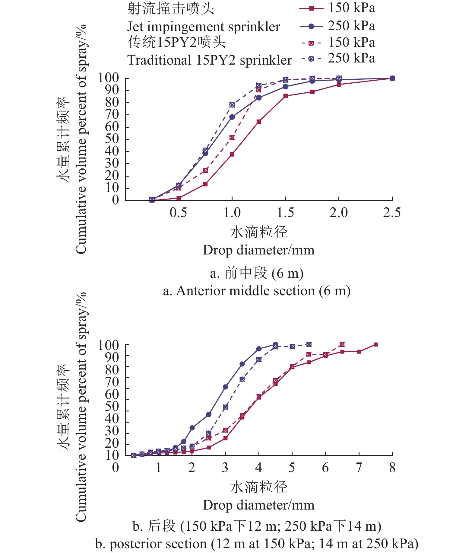
对8组水滴粒径数据进行测量,得到的水滴粒径区间为0~7.5 mm,将此区间分为19个等级,数据在喷头旋转状态下测量,为了降低试验误差,在同一位置同一压力下测量3次进行平均,结果如图6所示。
![]() 图 6 射流撞击喷头与传统15PY2喷头雨滴谱对比Figure 6. Comparison of droplet size distribution between the jet impingement sprinkler and the traditional 15PY2 sprinkler
图 6 射流撞击喷头与传统15PY2喷头雨滴谱对比Figure 6. Comparison of droplet size distribution between the jet impingement sprinkler and the traditional 15PY2 sprinkler水量累积频率为 10%、50%以及 90%对应的粒径比较如表9所示,试验结果表明压力升高,水量累积频率为 10%、50%以及 90%对应的粒径均减小,这与JIANG等[28]的研究结果是一致的,即喷头雾化程度随着压力的增加而增加,前中段水滴粒径较小,后段水滴粒径较大,这与向清江等[3]的试验结果相似。从图6中可以看到,在射程前中段,射流撞击喷头与传统15PY2喷头水滴粒径分布较为相似,且没有出现较大粒径的水滴,射流撞击喷头的水滴粒径普遍大于传统15PY2喷头,传统15PY2喷头中段的小水滴是由射流主体剥落形成的,而稍大的水滴是由副喷嘴雾化形成,射流撞击喷头中段的水滴均属于射流主体剥落形成,而其水滴粒径较大的原因在于副射流撞击导致的主射流发展不稳定,部分边缘射流因撞击波影响而提前破碎,避免了过小的水滴粒径导致的较多的蒸发飘移损失[29-30]。在射程后段,水滴的粒径区间较大,150 kPa下射流撞击喷头与传统15PY2喷头相比整体水滴粒径更大,但在250 kPa下射流撞击喷头整体水滴粒径更小,其原因在于,传统15PY2喷头只有主射流能够到达射程后段,而射流撞击喷头到达射程后段的是主副射流撞击后合成的射流,其总体流量更大,结果造成了同时有更好的雾化和更大的水滴粒径,而压力增大,撞击波造成的影响增大,克服了流量大带来的影响,导致了较小的水滴粒径区间分布。
表 9 射流撞击喷头与传统15PY2喷头的平均粒径对比Table 9. Comparison of average drop size between jet impingement sprinkler and traditional 15PY2 sprinkler喷头类型
Sprinkler type喷头工作压力
Working pressure/kPa雨滴测量位置
Measurig position/m累计频率10%粒径
Cumulative percentage 10% drop size d10/mm累计频率50%粒径
Cumulative percentage 50% drop size d50/mm累计频率90%粒径
Cumulative percentage 90% drop size d90/mm射流撞击喷头
Jet impingement sprinkler150 6 0.68 1.11 1.79 12 2.67 3.94 6.02 250 6 0.45 0.85 1.41 14 1.63 2.76 3.78 传统15PY2喷头
Traditional 15PY2 sprinkler150 6 0.49 0.99 1.25 12 2.12 3.91 5.45 250 6 0.45 0.81 1.18 14 2.06 3.13 4.15 3. 结 论
1)正交试验得到影响喷头综合工作性能的结构参数依次为副喷管长度,副喷嘴进口锥角,副喷管内径,副喷嘴仰角。且射流撞击喷头最优结构尺寸为:副喷管长度20 mm,副喷嘴进口锥角55°,副喷管内径6 mm,副喷嘴仰角33°。
2)在150~300 kPa的全压力下,射流撞击式喷头的组合均匀系数及综合评分均值均高于传统15PY2喷头,其中组合均匀系数平均提升4.84%,综合评分均值平均提升4%。
3)对比了射流撞击喷头和传统15PY2喷头前中段和后段的水滴分布,发现射流撞击导致主射流发展不稳定,部分边缘射流因撞击波影响而提前破碎,使射流撞击喷头前中段水滴粒径普遍大于传统15PY2喷头,避免了过小的水滴粒径导致的较多的蒸发飘移损失,然而射流撞击对水滴分布的影响机理尚不明确,后续将通过射流撞击喷头与射流不撞击喷头对比进一步研究液滴分布变化规律。
-
![]()
图 1 射流撞击喷头工作原理示意图
1.主射流 2.副射流 3.射流撞击点 4液膜 5液滴
Figure 1. Schematic diagram of working principle of jet impingement sprinkler
1. Primary jet 2. Secondary jet 3. Jet impingement point 4. Liquid sheet 5.Droplets
![]()
图 2 喷头主体结构
1.摇臂 2.主喷嘴 3.主喷管 4.副喷嘴5.下喷体 6.下轴承
Figure 2. Main structure of sprinkler
1. Rocker arm 2. Primary nozzle 3. Primary spray tube 4. Secondary nozzle 5. Lower spray body 6.Lower bearing 注: α 为副喷嘴仰角,(°); θ 为副喷嘴进口锥角,(°); D 为副喷管内径,mm; L 为副喷管长度,mmNote: α is secondary nozzle elevation angle, (°); θ is secondary nozzle inlet cone angle, (°); D is inner diameter of secondary spray tube, mm; L is secondary spray tube length, mm
![]()
图 5 不同压力下射流撞击喷头与射流不撞击喷头水量分布曲线
Figure 5. Water distribution curve of jet impingement sprinkler and jet non-impingement sprinkler under different pressures
![]()
图 6 射流撞击喷头与传统15PY2喷头雨滴谱对比
Figure 6. Comparison of droplet size distribution between the jet impingement sprinkler and the traditional 15PY2 sprinkler
表 1 因素水平表
Table 1 Factor and level
水平
Level因素Factors 副喷嘴仰角
Secondary nozzle elevation angle
α/(°)副喷管内径
Inner diameter of secondary spray tube
D/mm副喷管长度
Secondary spray tube length
L/mm副喷嘴进口锥角
Secondary nozzle inlet cone angle
θ/(°)1 27 4 10 35 2 30 6 20 45 3 33 8 30 55  下载: 导出CSV
表 2 试验方案
Table 2 Test scheme
试验号
Test No.α/(°) D/mm L/mm θ/(°) 1 27 4 10 35 2 27 6 20 45 3 27 8 30 55 4 30 4 20 55 5 30 6 30 35 6 30 8 10 45 7 33 4 30 45 8 33 6 10 55 9 33 8 20 35
下载: 导出CSV
表 3 各压力下流量
Table 3 Flow at various pressures
(m3·h-1) 试验号
Test No.150 kPa 200 kPa 250 kPa 300 kPa 1 1.10 1.27 1.42 1.55 2 1.12 1.29 1.44 1.57 3 1.11 1.27 1.42 1.55 4 1.07 1.24 1.37 1.53 5 1.15 1.31 1.45 1.58 6 1.12 1.27 1.44 1.56 7 1.10 1.27 1.42 1.53 8 1.11 1.27 1.44 1.53 9 1.10 1.27 1.42 1.54 平均值Avg. 1.11 1.27 1.42 1.55
下载: 导出CSV
表 4 各压力下射程与组合均匀系数
Table 4 Wetted radius and combination uniformity coefficients under various pressures
试验号
Test No.150 kPa 200 kPa 250 kPa 300 kPa R/m Cu/% R/m Cu/% R/m Cu/% R/m Cu/% 1 14.25 59.22 15.40 65.44 16.00 65.61 16.00 67.34 2 14.98 63.72 15.48 65.87 17.50 70.24 17.38 71.68 3 14.38 61.06 15.71 67.12 16.33 65.79 17.43 71.00 4 14.94 63.37 15.50 65.96 17.21 67.97 17.21 70.63 5 15.45 65.42 15.93 65.03 16.33 65.13 17.16 65.28 6 14.97 68.67 16.31 47.47 16.00 68.57 16.50 69.71 7 14.00 62.67 15.08 65.91 15.65 68.79 15.75 70.66 8 13.13 67.20 14.33 68.69 14.39 70.47 14.73 71.54 9 14.00 62.45 15.58 66.97 16.10 69.61 16.19 69.47
下载: 导出CSV
表 5 射程和组合均匀系数极差分析
Table 5 Wetted radius and combination uniformity coefficient range analysis
指标Index α D L θ 射程
Wetted radius
RK1 47.71 46.75 45.50 47.10 K2 48.38 46.70 48.02 47.40 K3 44.73 47.38 47.30 46.32 k1 15.90 15.58 15.17 15.70 k2 16.13 15.57 16.01 15.80 k3 14.91 15.79 15.77 15.44 r 1.22 0.23 0.84 0.36 组合均匀
系数
Combination uniformity
coefficient CuK1 198.52 198.39 197.48 196.74 K2 195.80 202.57 201.99 198.49 K3 203.61 196.97 198.47 202.70 k1 66.17 66.13 65.83 65.58 k2 65.27 67.52 67.33 66.16 k3 67.87 65.66 66.16 67.57 r 2.60 1.86 1.50 1.99 注:K 为每个因素各水平的数值之和; k 为每个因素水平的平均值; r 为极差。
Note: K is the sum of the values of each factor at each level; k is the average value of each factor level; r is extreme range.
下载: 导出CSV
表 6 各压力下的综合评分及其均值
Table 6 Comprehensive scores and its average value under various pressures
试验号
Test No.工作压力
Pressure/kPaˉy 150 200 250 300 1 37.03 41.38 44.34 41.45 41.05 2 39.67 41.64 47.62 44.30 43.31 3 38.03 42.40 44.58 43.99 42.25 4 39.47 41.70 46.20 43.69 42.77 5 40.76 41.42 44.20 41.02 41.85 6 42.17 32.49 46.03 42.88 40.89 7 38.65 41.47 46.00 42.97 42.27 8 40.52 42.55 46.42 42.89 43.10 9 38.54 42.26 46.66 42.60 42.52
下载: 导出CSV
表 7 综合评分均值极差分析
Table 7 Range analysis of average comprehensive scores
指标Index 因素Factors α D L θ K1 126.61 126.09 125.04 125.42 K2 125.51 128.26 128.59 126.47 K3 127.89 125.66 126.37 128.11 k1 42.20 42.03 41.68 41.81 k2 41.84 42.75 42.86 42.16 k3 42.63 41.89 42.12 42.70 r 0.79 0.87 1.19 0.90
下载: 导出CSV
表 8 射流撞击式喷头与传统15PY2喷头水力性能对比
Table 8 Comparison of hydraulic performance between the jet impingement sprinkler and the traditional 15PY2 sprinkler.
喷头类型
Sprinkler type150 kPa 200 kPa 250 kPa 300 kPa R/m Cu/% yi R/m Cu/% yi R/m Cu/% yi R/m Cu/% yi 射流撞击喷头
Jet impingement sprinkler13.47 66.54 40.35 14.65 68.96 42.85 15.47 70.03 46.63 15.70 71.61 43.42 传统15PY2
Traditional 15PY213.95 64.43 39.52 14.68 67.71 42.22 15.21 65.40 43.88 15.43 66.83 40.91 注:R为射程,Cu为组合均匀系数,yi为综合评分。 Note: R is wetted radius, Cu is combination uniformity coefficients, yi is comprehensive score.
下载: 导出CSV
表 9 射流撞击喷头与传统15PY2喷头的平均粒径对比
Table 9 Comparison of average drop size between jet impingement sprinkler and traditional 15PY2 sprinkler
喷头类型
Sprinkler type喷头工作压力
Working pressure/kPa雨滴测量位置
Measurig position/m累计频率10%粒径
Cumulative percentage 10% drop size d10/mm累计频率50%粒径
Cumulative percentage 50% drop size d50/mm累计频率90%粒径
Cumulative percentage 90% drop size d90/mm射流撞击喷头
Jet impingement sprinkler150 6 0.68 1.11 1.79 12 2.67 3.94 6.02 250 6 0.45 0.85 1.41 14 1.63 2.76 3.78 传统15PY2喷头
Traditional 15PY2 sprinkler150 6 0.49 0.99 1.25 12 2.12 3.91 5.45 250 6 0.45 0.81 1.18 14 2.06 3.13 4.15
下载: 导出CSV
-
[1] SHAH F, WU W. Use of plastic mulch in agriculture and strategies to mitigate the associated environmental concerns[J]. Advances in Agronomy, 2020, 164: 231-287.
[2] 王新坤,姚吉成,徐胜荣,等. 负压反馈射流喷头脉冲特性及其影响规律[J]. 农业工程学报,2020,36(4):90-97. WANG Xinkun, YAO Jicheng, XU Shengrong, et al. Pulse characteristics and its influence of negative pressure feedback jet sprinkler[J]. Transactions of the Chinese Society of Agricultural Engineering (Transactions of the CSAE), 2020, 36(4): 90-97. (in Chinese with English abstract)
[3] 向清江,许正典,陈超,等. 掺气水射流应用于低压摇臂喷头的试验[J]. 农业工程学报,2016,32(16):54-58. doi: 10.11975/j.issn.1002-6819.2016.16.008 XIANG Qingjiang, XU Zhengdain, CHEN Chao, et al. Experiment on aeration water jet applied to low pressure impact sprinkler irrigation[J]. Transactions of the Chinese Society of Agricultural Engineering (Transactions of the CSAE), 2016, 32(16): 54-58. (in Chinese with English abstract) doi: 10.11975/j.issn.1002-6819.2016.16.008
[4] UYGAN D, CETIN O, ALVEROGLU V, et al. Improvement of water saving and economic productivity based on quotation with sugar content of sugar beet using linear move sprinkler irrigation[J]. Agricultural Water Management, 2021, 255: 106989. doi: 10.1016/j.agwat.2021.106989
[5] 汤攀,李红,陈超,等. 垂直摇臂式喷头驱动力计算及试验修正[J]. 农业工程学报,2015,31(17):20-26. doi: 10.11975/j.issn.1002-6819.2015.17.003 TANG Pan, LI Hong, CHEN Chao, et al. Calculation and modification by experiment of driving force for vertical impact sprinkler[J]. Transactions of the Chinese Society of Agricultural Engineering (Transactions of the CSAE), 2015, 31(17): 20-26. (in Chinese with English abstract) doi: 10.11975/j.issn.1002-6819.2015.17.003
[6] Nelson Irrigation Corporation[EB/OL]. [2024-03-08]. https://nelsonirrigation.com/products/rotator-sprinklers/r2000-rotator
[7] 李红,徐敏,李一鸣,等. 喷头旋转式散水盘散水齿结构优化设计[J]. 农业机械学报,2014,45(12):69-74. doi: 10.6041/j.issn.1000-1298.2014.12.011 LI Hong, XU Min, LI Yiming, et al. Optimal design of rotating stream interrupter diffuser for sprinklers[J]. Transactions of the Chinese Society for Agricultural Machinery, 2014, 45(12): 69-74. (in Chinese with English abstract) doi: 10.6041/j.issn.1000-1298.2014.12.011
[8] 范兴科,吴普特,朱琳,等. 雾化度可调节的低仰角喷头[P]:CN2649185Y,[2004-10-20]. [9] JIANG Y, ISSAKA Z, LI H, et al. Range formula based on angle of dispersion and nozzle configuration from an impact sprinkler[J]. International Journal of Agricultural and Biological Engineering, 2019, 12(5): 97-105. doi: 10.25165/j.ijabe.20191205.4646
[10] PAN X, JIANG Y, LI H, et al. Numerical simulation and experimental study of jet breakup using a water dispersal needle in irrigation sprinklers[J]. Biosystems Engineering, 2024, 239: 49-67. doi: 10.1016/j.biosystemseng.2024.01.017
[11] PAN X, JIANG Y, LI H, et al. Numerical simulation of the effect of varying dispersion tooth insertion depth on the jet breakup and hydraulic performance[J]. Biosystems Engineering, 2024, 239: 98-113. doi: 10.1016/j.biosystemseng.2024.02.005
[12] 李佳楠,雷凡培,杨岸龙,等. 强迫扰动下的射流撞击雾化特性[J]. 航空学报,2020,41(12):84-105. LI Jianan, LEI Fanpei, YANG Anlong, et al. Atomization characteristics of impinging liquid jets coupled with forced perturbation[J]. Acta Aeronautica et Astronautica Sinica, 2020, 41(12): 84-105. (in Chinese with English abstract)
[13] 王宇奇,勾文进,陈明慧,等. 孔径比和动量比对双股射流撞击式雾化影响分析[J]. 固体火箭技术,2021,44(1):26-32. doi: 10.7673/j.issn.1006-2793.2021.01.005 WANG Yuqi, GOU Wenjin, CHEN Minghui, et al. Analysis of impact on two jets impinging atomization under variable diameter and momentum ratios[J]. Journal of Solid Rocket Technology, 2021, 44(1): 26-32. (in Chinese with English abstract) doi: 10.7673/j.issn.1006-2793.2021.01.005
[14] SUN Z B, LIAO H L, WANG L H, et al. Liquid flow and breakage behaviors of two liquid jets impacting on the wire mesh with different impinging angles[J]. Chemical Engineering Journal, 2023, 454: 140036. doi: 10.1016/j.cej.2022.140036
[15] 董福龙,周宏平,施明宏,等. 对冲喷头设计与雾化试验[J]. 林业科学,2019,55(1):81-88. DONG Fulong, ZHOU Hongping, SHI Minghong, et al. Design and atomization test of impinging nozzle[J]. Scientia Silvae Sinicae, 2019, 55(1): 81-88. (in Chinese with English abstract)
[16] 董福龙. 基于射流和撞击流耦合作用的对冲喷头研究[D]. 南京:南京林业大学,2018. DONG Fulong. Study on Impinging Nozzle Based on the Coupling of Jet and Impinging Jet [D]. Nanjing: Nanjing Forestry University, 2018. [17] DIAS G S, MACHADO D A, DE Andrade J C, et al. Experimental study of impinging jets of gelled and liquid fluids[J]. International Journal of Multiphase Flow, 2023, 165: 104478. doi: 10.1016/j.ijmultiphaseflow.2023.104478
[18] ALMOHAMMED N, BREUER M. Towards a deterministic composite collision outcome model for surface-tension dominated droplets[J]. International Journal of Multiphase Flow, 2019, 110: 1-17. doi: 10.1016/j.ijmultiphaseflow.2018.08.007
[19] DOMBROWSKI N D, HOOPER P C. A study of the sprays formed by impinging jets in laminar and turbulent flow[J]. Journal of Fluid Mechanics, 1964, 18(3): 392-400. doi: 10.1017/S0022112064000295
[20] JIANG Y, LI H, HUA L, et al. Three-dimensional flow breakup characteristics of a circular jet with different nozzle geometries[J]. Biosystems Engineering, 2020, 193: 216-231. doi: 10.1016/j.biosystemseng.2020.03.003
[21] 孟天舒. 内驱动射流脉冲喷头结构设计及试验研究[D]. 镇江:江苏大学,2022. Meng Tianshu. Structural Design and Experimental Study of Internally Driven Jet Pulse Sprinkler [D]. Zhenjiang: Jiangsu University, 2022.
[22] 李星恕,张建宾,韩文霆. 仰角可调摇臂式喷头水力性能试验[J]. 农业机械学报,2015,46(2):34-39. LI Xingshu, ZHANG Jianbin, HAN Wenting. Experiments on hydraulic performance of impact sprinkler with adjustable elevation angle[J]. Transactions of the Chinese Society for Agricultural Machinery, 2015, 46(2): 34-39. (in Chinese with English abstract)
[23] ZHU X, YUAN S, LIU J, LIU X. Comparison of droplet distributions from fluidic and impact sprinklers[J]. Frontiers of Agricultural Science Engineering, 2015, 2(1): 53-59. doi: 10.15302/J-FASE-2015049
[24] 高飞,张锐,朱德兰,等. Teejet雾化喷头的水力性能试验及工作参数优选[J]. 农业工程学报,2022,38(22):280-286. doi: 10.11975/j.issn.1002-6819.2022.22.030 GAO Fei, ZHANG Rui, ZHU Delan, et al. Hydraulic performance tests and optimized working parameters of Teejet atomizing nozzles[J]. Transactions of the Chinese Society of Agricultural Engineering (Transactions of the CSAE), 2022, 38(22): 280-286. (in Chinese with English abstract) doi: 10.11975/j.issn.1002-6819.2022.22.030
[25] 刘俊萍,袁寿其,李红,等. 摇臂式喷头组合喷洒均匀性的改进[J]. 农业工程学报,2011,27(7):107-111. doi: 10.3969/j.issn.1002-6819.2011.07.018 LIU Junping, YUAN Shouqi, LI Hong, et al. Combination uniformity improvement of impact sprinkler[J]. Transactions of the Chinese Society of Agricultural Engineering (Transactions of the CSAE), 2011, 27(7): 107-111. (in Chinese with English abstract) doi: 10.3969/j.issn.1002-6819.2011.07.018
[26] 高飞,朱德兰,闫婧歆,等. 安装高度和工作压力对育苗喷头水力性能影响的试验研究[J]. 灌溉排水学报,2022,41(1):119-125. GAO Fei, ZHU Delan, YAN Jingxin, et al. Impact of mounting height and working water pressure on the performance of micro-sprinkler irrigation system for seedling beds[J]. Journal of Irrigation and Drainage, 2022, 41(1): 119-125. (in Chinese with English abstract)
[27] 黄春梅. 基于分层机制的边缘计算任务卸载策略研究[D]. 重庆:重庆邮电大学,2022. Huang Chunmei. Research on Computing Task Offloading Strategy Based on Hierachical Mechanism[D]. Chongqing: Chongqing University of Posts and Telecommunications, 2022. [28] JIANG Y, LIU J, LI H, et al. Droplet distribution characteristics of impact sprinklers with circular and noncircular nozzles: Effect of nozzle aspect ratios and equivalent diameters[J]. Biosystems Engineering, 2021, 212: 200-214.
[29] XIANG Q , QURESHI A W , TUNIO H M , et al. low-pressure drop size distribution characterization of impact sprinkler jet nozzles with and without aeration[J]. Agricultural Water Management, 2021, 243: 106458.
[30] TOPAK R, SÜHERI S, KARA M, et al. Investigation of the energy efficiency for raising crops under sprinkler irrigation in a semi-arid area[J]. Applied Engineering in Agriculture, 2005, 21(5): 761-768. doi: 10.13031/2013.19701


计量
- 文章访问数: 140
- HTML全文浏览量: 16
- PDF下载量: 50