Pickup device with shovel teeth and double cylindersfor the bunch of peanuts
-
摘要:
两段收获是国内花生机械化收获主要方式。大中型花生捡拾收获机所配置的弹齿滚筒式捡拾装置结构复杂且易损坏,捡拾过程中不仅存在植株抛起、壅堆、漏捡和掉果等问题,弹齿弹出地面时也会造成扬尘,严重制约了花生收获作业效率、增加花生损失,加剧环境污染。针对上述问题,该研究在分析弹齿滚筒捡拾花生过程基础上,提出了由铲齿、拨秧滚和捡拾滚(简称双滚筒)构成的花生捡拾机构,研制出相应的捡拾装置样机并进行田间性能试验;基于Box-Behnken中心组合设计原理,以植株捡拾率和荚果落果率为试验指标以机组前进速度,捡拾速比和铲齿半径为试验因素进行了正交试验,并对试验因素进行优化。试验结果表明,铲齿-双滚筒组合式花生捡拾装置作业中不存在植株抛起、壅堆和弹齿扬尘等问题;在田间试验条件下,作业速度为1.2 m/s、捡拾速比为1.2、铲齿半径为498 mm时,花生植株捡拾率均值为99.22%,落果率均值为1.84%,均优于花生捡拾作业标准要求。铲齿-双滚筒研究结果对解决国内花生捡拾收获机存在的捡拾问题具有重要意义。
Abstract:Two-stage peanut harvesting is one of the most popular mechanized ways in China. Among them, the commonly used pickup device can be equipped with the spring teeth cylinder in large and medium-sized picking and harvesting machines. There are some challenges, including plant throwing, stacking, missing picking, and fruit falling damage. At the same time, the spring teeth can circularly scratch into and out of the ground during the operation of the pickup device, leading to dust. The efficiency of peanut picking and harvesting can be seriously restricted to increase the loss of pods falling during harvesting. The action of the pickup time on the ground has also exacerbated the dust pollution. This study aims to combine the structure of the toothed drum mechanism in the new type of pickup device with the shovel teeth and double-cylinders for bunch upright peanuts. According to the upright peanut plant shape, strip laying, motion posture and dynamics during picking, the peanut pickup device consisted of shovel teeth, a pushing cylinder, and a picking cylinder (referred to as a double cylinder). The better performance of picking peanuts was achieved in the sequential coordination with four beats of shovel pluck pick delivery. The traditional single-toothed drum pickup device was replaced in this case. The shovel tooth structure of the circular arc working surface was designed to determine the range of shovel tooth radius using geometric relationships. The structure of pushing teeth and picking teeth was designed with a backward inclination angle. The structure and rotation radius of two rollers were determined to design the semi-enclosed protective plate structure with the specific parameters. The motion parameters of the unit were obtained to simulate the range of picking speed ratio after ADAMS simulation. A prototype of a combined peanut pickup device was conducted to develop the shovel teeth, picking cylinder, pushing cylinder, and half guard board in field performance tests. According to Box Behnken central combination design, an orthogonal experiment was conducted on the peanut plant picking rate and peanut pod drop rate as experimental indicators, while the unit forward speed, picking speed ratio, and shovel teeth radius as experimental factors. The test results indicate that the shovel teeth double cylinder combined peanut pickup device operated smoothly, where there were no plant throwing, pile up, and dust from bullet teeth during peanut picking; The mean value of picking rate of peanut plant was 99.22%, and the mean value of pod loss rate was 1.84%, when the forward speed was 1.2 m/s, the picking speed ratio was 1.2, and the shovel teeth radius was 498 mm under field experimental conditions. The findings fully met the requirements for peanut picking.
-
Keywords:
- agricultural machinery /
- harvester /
- peanut /
- pickup device
-
0. 引 言
东北地区苏打盐碱地是中国盐碱地的主要集中区,对盐碱土壤进行改良研究与实践,使之适宜农作物的生长发育,对提高粮食安全具有重要意义[1-2]。针对东北苏打盐碱地特征,课题组设计了一种具有叶脉状内通道的深松铲[3],可以实现自润减阻配合改良液层施,进而达到改良东北地区苏打盐碱土的目的。目前多孔分布管广泛应用于给排水、滴喷灌等领域[4]。为研究其出流特性,国内外众多学者开展了大量分析研究[5]。不同学者针对不同情况下对多孔管内流体分布的计算方程进行推导, RAVIKUMAR等[6]建立了分析方程来确定压力的变化系数,推导出计算流量变化系数的简单解析方程,用于求解数值问题中的流量变异系数;CHELLAM等[7]研究了具有1道和2道可渗透壁的均匀多孔管内不可压缩层流的特性,建立了四阶微分方程并得到了所有壁面雷诺数的解;刘文华等[8]结合水力学分析理论,对坡度、压力水头、孔距、管长4个参数对沿程压力分布的影响规律开展研究;杜涛等[9]建立多孔管出流控制体模型并对达西-韦斯巴赫公式进行完善,得出了多孔管沿程水头损失的计算公式;一些学者通过物理试验方法对多孔管的液体出流进行了相应研究,王亚朦等[10]根据达西-韦斯巴赫公式,结合理论分析与试验的方法,对不同坡度下多孔分布管内流体压力分布规律开展研究;鞠学良等[11]根据微灌毛管水力解析模型,提出了考虑适宜布置形式的均匀坡微灌毛管设计方案以提高灌水均匀度;杨宝中等[12]结合单孔出流试验结果,对多孔管土中出流计算公式进行分析研究,为多孔管地下灌溉提供参考;随着计算流体动力学的发展,数值模拟技术已成为研究单相流和结构优化的重要工具,钱卫忠等[13]使用有限元分析的方法分析多孔管孔径、管长、水压等因素对多孔管出流速度和流量的影响,并得到影响多孔管出流速度及出流量影响显著的因素;王鹏辉[14]提出了基于CFD的“流场分析设计方法”并对喷淋装置几何结构进行了设计优化;韩圆圆[15]通过数值模拟的方法分析了T型三通管内的气液流动特性及相分布规律。
综上,关于多孔管出流速度及出流量的研究多与水利灌溉工程相关,目前未见将其与深松部件结合的相关研究。针对叶脉状内通道的流场分布规律及影响因素不明确的问题,本文拟采用基于计算流体动力学的仿真方法结合物理试验对其进行研究。首先利用仿真的方法,开展单因素试验,优选出影响内通道分支出口流速的因素水平范围值,其次开展Box-Behnken试验,建立各影响因素与分支出口流速之间的二阶回归模型,进而得到最优参数组合。按最优参数组合条件对叶脉状内通道进行设计加工后进行相应的物理试验,得出物理试验值。通过仿真与物理试验结果的对比,检验叶脉状内通道结构优化设计的效果,从而达到对叶脉状内通道优化设计的目的,为利用叶脉状内通道多分支出口管结构在东北地区苏打盐碱地进行深松及化学改良耦合技术提供理论基础。
1. 数值计算模型与计算方法
1.1 数值计算模型
以课题组自研的叶脉状内通道自润滑减阻深松铲的内部结构——叶脉状内通道多分支出口管为研究对象。其深松铲结构由铲柄、弧形铲刃、凿型铲尖及叶脉状多分支出口内通道组成。深松铲铲体长度为1200 mm,其中铲柄长500 mm,弧形铲刃长600 mm,铲尖长100 mm,铲刃横截面为等腰三角形且刃口角度为42°。叶脉状内通道与深松铲铲柄及弧形铲刃的总长度尺寸一致,由主通道直管部分及弧形叶脉状多分支出口管两部分构成,其总长度为1100 mm,主通道直径10 mm,直管部分长度500 mm,弧形叶脉状多分支出口管部分是半径550 mm的圆弧,其长度为600 mm。其中每组分支出口由两个在主通道X轴线上呈42°夹角对称分布的分支出口组成,同时每组分支出口在Y轴上以相同间距在叶脉状内通道多分支出口弧形管段上均匀分布。其叶脉状内通道深松铲及内通道多分支出口管结构如图1。
![]() 图 1 叶脉状内通道深松铲与叶脉状内通道多分支出口管结构图1.主通道 2.深松铲体 3.深松铲刃口夹角42° 4.直管部分 5.弧形管部分 6.末端分支出口 7.分支出口夹角42° 8.首端分支出口 9.主通道入口Figure 1. Structure diagram of deep loosening shovel and a porous pipe flow channel model in leaf vein shaped inner channel1.Main channel 2.Deep loosening shovel body 3. Deep loosening shovel blade angle 42° 4. Straight pipe section 5. Curved tube section 6. End branch outlet 7. Branch outlet angle 42° 8. The head branch outlet 9. Main channel entrance
图 1 叶脉状内通道深松铲与叶脉状内通道多分支出口管结构图1.主通道 2.深松铲体 3.深松铲刃口夹角42° 4.直管部分 5.弧形管部分 6.末端分支出口 7.分支出口夹角42° 8.首端分支出口 9.主通道入口Figure 1. Structure diagram of deep loosening shovel and a porous pipe flow channel model in leaf vein shaped inner channel1.Main channel 2.Deep loosening shovel body 3. Deep loosening shovel blade angle 42° 4. Straight pipe section 5. Curved tube section 6. End branch outlet 7. Branch outlet angle 42° 8. The head branch outlet 9. Main channel entrance1.2 数值模型网格划分
数值模拟计算中选取的叶脉状内通道多孔管的流体计算流域为主通道入口至叶脉状多分支出口处。采用ICEM中的O-Block技术进行流体计算域网格划分[16],可获得较规整的结构网格和较好的边界层网格。计算域采用适应度较强的非结构四面体网格进行划分,算法采用补丁适形法,采用美国机械工程协会(American Society of Mechanical Engineers,ASME)推荐的网格收敛指数 GCI 进行网格离散误差的估计,对网格进行无关性验证[17-19]。最终确定选取中等网格,此时的模型网格总数为198353个,节点总数为43799个,并检查网格问题与质量,结果显示平均网格质量、偏度和纵横比分别为0.837、0.228、1.85, 所生成网格的质量较高,符合本文计算要求。
1.3 数值计算方法及试验设计
1.3.1 数值计算方法
图2为多孔管计算域网格。液体入口位于直管部分顶端,出口位于弧形管部分上的各分支出口上,其余位置均密闭,壁面处设置为无滑移壁面,计算流体使用不可压缩的液态水,进口边界选择流速入口边界条件,对于出口边界条件,采用压力出口边界条件压力值为0,参考压力为标准大气压[20]。采用k-ε湍流模型,依靠计算流体力学求解软件Fluent进行求解[21-24]。在多孔管设置中给定主通道入口流速,经过软件模拟可得到多孔管在该主通道入口流速下达到稳定状态时的内通道各分支出口流速。
1.3.2 试验设计
文章中所讨论的叶脉状内通道分支多孔管,目的是在深松过程中,利用分支出口流出的液体改良剂在铲刃面上形成液膜达到自润滑减阻目的,同时利用流出的改良剂对盐碱地进行化学改良。这就需要每组分支出口的流速要达到一定要求,同时每组分支出口的流量也要达到一定要求,通过大量田间试验发现,叶脉状内通道的结构参数(孔径、孔间距、孔数)及运行参数(主通道入口流速)对分支出口的出流速度及液膜的形成起到决定性作用。因此本文选择分支出口的孔径、孔间距、孔数及主通道入口流速为研究因素。其中孔径即为分支出口的直径,孔间距即为相邻两组分支出口的距离,孔数即为分支出口的组数,主通道入口流速即为改良剂流入主通道的速度。
结合实际工况及多次预试验发现,分支出口6 mm以下的孔径所流出的液体在深松过程中不能够形成将整个深松铲铲面完全覆盖的液膜,即不能保证流量要求,因此选择6 mm以上的孔径进行讨论。分支出口孔间距距离太小及孔数过少则达不到分层减阻及化学改良液层施时所需效果,同时分支出口孔间距距离太大及孔数过多则使最末端分支出口流量太小。在确保各组分支出口的表面积流速大于1 m/s以及所流出的液体能够使铲刃面形成液膜的前提下,初步确定叶脉状内通道分支出口孔径、孔间距、孔数和主通道入口流速4个因素的水平取值范围,进而开展单因素仿真模拟试验,对因素水平进行初步优选,以确定各因素最佳工作水平范围,具体因素水平见表1。研究单因素对各组分支出口流速的影响时,其他因素取中间水平值。
表 1 叶脉状内通道多孔管数值模拟参数Table 1. Numerical simulation parameters of leaf vein shaped inner channel porous tube水平
Factors分支出口孔径
Branch outlet
aperture D/mm分支出口孔间距
Branch outlet
hole spacing
A/mm孔数
Hole number
B主通道入口流速
Main channel
inlet velocity
C/(m·s−1)1 6 80 3 3 2 7 90 4 4 3 8 100 5 5 4 9 110 6 6 5 10 120 7 7 内通道分支出口截面上的最大流速即为表面积最大流速,内通道分支出口截面上的平均流速即为平均流速,两种流速表达的含义不同。距主通道入口最近的一组分支出口即为首端出口,距主通道入口最远的一组分支出口即为末端出口;主通道入口流速在沿程上经过首端或末端分支出口的分流而减少的值即为首端或末端出口分流损失;主通道入口流速在沿程上经过各分支出口的分流而减少的值与主通道入口流速的比值即为流速的分流损失率,以此来量化表征主通道入口流速经过各分支出口被分流的多少,进而分析不同影响因素水平对流速的影响大小。即:首端出口分流损失等于主通道入口流速减去首端分支出口流速;末端出口分流损失等于主通道入口流速减去末端分支出口流速;首末端出口分流损失等于首端分支出口流速减去末端分支出口流速;首端出口分流损失率等于首端出口分流损失与主通道入口流速的比值;末端出口分流损失率等于末端出口分流损失与主通道入口流速的比值;首末端出口分流损失率等于首末端出口分流损失与首端分支出口流速的比值。
2. 结果与分析
2.1 叶脉状内通道多分支出口管沿程流速变化规律
图3为叶脉状内通道主通道流速剖面图。由图3发现叶脉状主通道上沿程流速变化趋势为先逐渐增大后逐渐减小。以叶脉状内通道多分支出口管主通道直径10 mm、内通道分支出口孔径6 mm、孔间距100 mm、孔数5、主通道入口端流速5 m/s时为例,叶脉状主通道上最大流速值为5.736 m/s,最小流速为0。沿程流速从入口处开始逐渐增加直至首组分支出口处上端达到沿程流速最大值,经过首端分支出口下端后开始逐渐减小,在达到末端分支出口后沿程流速逐渐减小至最小值。出现主通道内部沿程流速先逐渐增大后逐渐减小的原因,可能是在射流和惯性重力及离心力的影响作用下,在主通道内部产生沿程流速加速现象,使主通道内部沿程流速先逐渐增大到流速最大值[25];随后液体经过首组内通道分支出口后压力减小,液体开始逐级分流,沿程流速开始逐渐减小。
![]() 图 3 叶脉状内通道主通道流速剖面图Figure 3. Flow velocity profile of main channel in leaf vein shaped inner channel
图 3 叶脉状内通道主通道流速剖面图Figure 3. Flow velocity profile of main channel in leaf vein shaped inner channel2.2 单因素试验结果
通过对初步确定的影响叶脉状内通道分支出口流速的因素进行单因素试验,根据试验数据分析各因素对分支出口流速的影响情况,进一步确定参数范围,试验结果如图4所示。
![]() 图 4 各因素下的内通道分支出口平均流速注:B1为首端分支出口;B2为第二分支出口;B3为第三分支出口;B4为第四分支出口;B6为第六分支出口;B5和B7为末端分支出口。Figure 4. Average flow velocity at the outlet of internal channel branches under various factorsNote:B1is the head branch outlet; B2 is the second branch outlet; B3 is the third branch outlet; B4 is the fourth branch outlet; B6 is the sixth branch outlet; B5 and B7 are the end branch outlet.
图 4 各因素下的内通道分支出口平均流速注:B1为首端分支出口;B2为第二分支出口;B3为第三分支出口;B4为第四分支出口;B6为第六分支出口;B5和B7为末端分支出口。Figure 4. Average flow velocity at the outlet of internal channel branches under various factorsNote:B1is the head branch outlet; B2 is the second branch outlet; B3 is the third branch outlet; B4 is the fourth branch outlet; B6 is the sixth branch outlet; B5 and B7 are the end branch outlet.2.2.1 分支出口孔径对流速的影响
根据图4a可知,随着内通道分支出口孔径的增加,同一分支出口下的流速逐渐减小,同一孔径下的各分支出口流速逐渐减小。当孔径由6 mm增加到10 mm时,表面积最大流速的首端出口分流损失率、末端出口分流损失率及首末端出口分流损失率均逐渐增加,当孔径为6 mm时,表面积最大流速的三种分流损失率分别为4.43%、38.52%和35.67%,均为最小。同时随着孔径的增加内通道分支出口平均流速的首端出口分流损失率、末端出口分流损失率及首末端出口分流损失率同样均逐渐增加,当孔径为6 mm时,平均流速的三种分流损失率分别为67.14%、58.32%和−26.83%,均为最小。孔径由6 mm增加到10 mm时,内通道分支出口表面积最大流速首端出口减小1.567 m/s,末端出口减小1.878 m/s;平均流速首端出口减小0.657 m/s,末端出口减小1.475 m/s。根据结果数据发现在主通道入口流速统一的情况下,内通道分支出口孔径越小,相邻两分支出口的出流速度差值变化越小,随着分支出口孔径的增加,同一孔径下相邻两分支出口出流速度差值逐渐增加,进而使各个分支出口平均流速减小。在孔径为6 mm时液体出流速度最快,因此液体流量也最大,能够达到自润滑减阻的目的。因此优选出叶脉状内通道多孔管模型内通道分支出口孔径为6 mm。
2.2.2 分支出口孔间距对流速的影响
根据图4b可知在内通道分支出口孔间距增加的情况下,内通道分支出口首端出口流速逐渐增大,末端出口流速逐渐减小,这是因为分支出口流速随着孔间距的增加在第二、三分支出口之后降幅开始加剧。同一孔间距下各分支出口流速整体上逐渐减小,只有当孔间距为80 mm时各分支出口流速先增加后减小。当孔间距为80 mm时,首端出口分流损失率同其他孔间距相比最大为26.30%;末端出口分流损失率及首末端出口分流损失率同其他孔间距相比最小,分别为60.22%和46.02%。当孔间距为120 mm时,首端出口分流损失率同比最小为15.46%;末端出口分流损失率及首末端出口分流损失率同其他孔间距相比最大,分别为68.58%和62.83%。同时随着孔间距的增加内通道分支出口平均流速的首端出口分流损失率、末端出口分流损失率及首末端出口分流损失率变化同表面积最大流速变化趋势一样。孔间距由80 mm增加到120 mm时,内通道分支出口表面积最大流速首端出口增加0.542 m/s,末端出口减小0.418 m/s;平均流速首端出口增加0.268 m/s,末端出口减小0.285 m/s。在主通道入口流速统一的情况下,内通道分支出口孔间距越小对各分支出口的首端出口出流速度影响变化较大,反而对末端出口出流速度影响变化较小,当孔间距由90 mm增加到110 mm时流速变化不大,这是叶脉状内通道分支出口这一结构造成的,但在对因素水平讨论优选的过程中是有必要的,因为在实际工作环境中分支出口的位置关系到改良剂液体对深松铲减阻的部位,以及利用叶脉状内通道这一结构进行化学改良过程中,达到化学改良剂分层施用这一目的。因此考虑综合实际试验因素,优选出叶脉状内通道多孔管模型内通道分支出口孔间距90、100、110 mm进行Box-Behnken仿真试验,进一步探究孔间距及其它因素水平交互下对分支出口流速的影响。
2.2.3 分支出口孔数对流速的影响
根据图4c可知在内通道分支出口孔数增加的情况下,内通道分支出口首末端流速均逐渐减小,同一孔数下各分支出口流速整体上是逐渐减小的,只有当孔数为3时各分支出口流速逐渐增加。孔数由3增加到7时,内通道分支出口表面积最大流速的首端出口分流损失率、末端出口分流损失率及首末端出口分流损失率均先增加后减小,当孔数为3时,三种分流损失率均为最小,分别为10.23%、21.49%和12.54%。当孔数为7时,此时首端出口分流损失率不是最大,分别为24.20%、67.44%和57.05%。同时随着孔数的增加内通道分支出口平均流速的首端出口分流损失率、末端出口分流损失率及首末端出口分流损失率变化同表面积最大流速变化趋势一样。孔数由3增加到7时,内通道分支出口表面积最大流速首端出口减少0.698 m/s,末端出口减小2.298 m/s;平均流速首端出口增加0.455 m/s,末端出口减小1.663 m/s。在主通道入口流速统一的情况下,内通道分支出口孔数越少对各分支孔的首末两端组出流速度影响变化越小,通过试验数据可以得出孔数在4~6时对流速影响变化幅度适中,同时为了考虑综合实际试验因素,优选出叶脉状内通道多孔管模型内通道分支出口孔数4、5、6进行Box-Behnken仿真试验,进一步探究孔数对分支出口流速的影响。
2.2.4 主通道入口流速对流速的影响
根据图4 d可知在内通道主通道入口流速增加的情况下,内通道各分支出口的流速是逐渐增大的,同一主通道入口流速下各分支出口流速先增加后逐渐减小。主通道入口流速由3 m/s增加到7 m/s时,内通道分支出口表面积最大流速的首端出口分流损失率逐渐增加,末端出口分流损失率逐渐减少,当主通道入口流速为3 m/s时,首端出口分流损失率同比最小为14.83%;末端出口分流损失率及首末端出口分流损失率同比最大为82.74%和79.74%。当主通道入口流速为7 m/s时,首端出口分流损失率同比最大为26.03%;末端出口分流损失率及首末端出口分流损失率同比最小为54.53%和38.53%。同时随着主通道入口流速的增加内通道分支出口平均流速的首端出口分流损失率先减少后增加,末端出口分流损失率及首末端出口分流损失率均减少。当主通道入口流速为7 m/s时,首端出口分流损失率为78.58%,末端出口分流损失率及首末端出口分流损失率74.38%和−19.58%,均为最小。在其他因素不变的情况下,主通道入口流速为5、6、7 m/s时首端出口分流损失率、末端出口分流损失率及首末端出口分流损失率均为中间值,因此优选出叶脉状内通道多孔管模型内通道分支出口主通道入口流速为5、6、7 m/s进行Box-Behnken仿真试验,进一步探究主通道入口流速对分支出口流速的影响。
3. Box-Behnken仿真试验
基于单因素仿真试验中优选出的各因素范围,设计二次回归正交试验,建立叶脉状内通道分支出口平均流速回归模型,以得到最优参数组合[26]。内通道分支出口孔径在单因素试验中已经优选出最优值为6 mm,其他因素水平如表2所示,Box-Behnken试验设计及结果如表3所示。
表 2 因素水平表Table 2. The factor level table水平
Level分支出口孔间距
Branch outlet
hole spacing
A/mm分支出口孔数
Holes number of branch
outlet B主通道入口流速
Main channel
inlet velocity
C/(m·s−1)−1 90 4 5 0 100 5 6 1 110 6 7 表 3 Box-Behnken试验设计及结果Table 3. Box Behnken experimental design and results序号No. X1 X2 X3 出口流速Outlet velocity/(m·s−1) 1 −1 −1 0 6.069 2 1 −1 0 5.896 3 −1 1 0 5.483 4 1 1 0 5.889 5 −1 0 −1 4.713 6 1 0 −1 4.961 7 −1 0 1 6.456 8 1 0 1 6.806 9 0 −1 −1 4.903 10 0 1 −1 4.769 11 0 −1 1 7.263 12 0 1 1 6.334 13 0 0 0 5.621 14 0 0 0 5.685 15 0 0 0 5.679 16 0 0 0 5.558 17 0 0 0 5.681 注:X1、X2、X3分别为分支出口孔间距、分支出口孔数、主通道入口流速的水平值。 Note: X1, X2, X3 are the levels of branch outlet hole spacing, branch outlet hole number, main channel inlet velocity respectively. Box-Behnken试验方差分析结果如表4所示,由表4的分析结果可知,X2、X3和X2X3对平均流速影响极其显著, X1、X1X2和X 22对平均流速影响显著;X1X3、X12和X32对平均流速影响不显著。模型的P<0.0001,说明回归模型高度显著;模型失拟项P>0.05,说明模型失拟性不显著,回归模型拟合程度高。回归方程决定系数R2=0.9911,校正决定系数R2=0.9796,与1非常接近,且变异系数CV=1.75%。根据统计学上F值越大、表明该因素对结果的影响越大[27-28],通过F值大小,可以判定各因素对平均流速影响的重要性,试验因素对平均流速影响从大到小为主通道入口流速、内通道分支出口孔数、内通道分支出口孔间距;综上表示该回归模型极其显著,能够可靠和真实的反映真实情况,可用于进一步的目标平均流速的预测分析。
表 4 Box-Behnken试验方差分析Table 4. Variance analysis of Box Behnken experiment方差源
Variance
source均方
Mean
square自由度
Degree of
freedom平方和
Sum of
squareF值
F-valueP值
P-value模型Model 7.830 9 0.870 86.21 <0.0001** X1 0.086 1 0.086 8.55 0.0222* X2 0.343 1 0.343 33.96 0.0006** X3 7.060 1 7.060 698.99 <0.0001** X1X2 0.084 1 0.084 8.30 0.0236* X1X3 0.003 1 0.003 0.26 0.6273 X2X3 0.158 1 0.158 15.65 0.0055** X1² 0.012 1 0.012 1.18 0.3141 X2² 0.078 1 0.078 7.75 0.0271* X3² 0.006 1 0.006 0.54 0.4849 残差
Residual0.071 7 0.010 失拟项
Lack of fit0.059 3 0.020 6.39 0.0525 纯误差
Pure error0.012 4 0.003 总和Sum 7.900 16 注: **表明影响极显著(P<0.01),*表明影响显著(P<0.05)。 Note: ** indicates that the impact is extremely significant (P<0.01), and * indicates that the impact is significant (P<0.05). 通过Design–Expert 11.0对Box-Behnken试验结果进行多元回归拟合,得到仿真试验出口流速二阶回归方程:
V=5.64+0.104X1−0.207X2+0.939X3+0.145X1X2+0.026X1X3−0.199X2X3+0.053X21+0.136X22+0.036X23 (1) 在Design–Expert 11.0软件的优化模块中,以分支出口平均流速最大值为优化目标值,将二阶回归方程式(1)中的不显著项剔除后进行优化求解,求解出最优参数组合为内通道分支出口孔间距110 mm、内通道分支出口孔数4、主通道入口流速7 m/s。
为验证仿真优化参数的可靠性,在最优参数条件下进行3次Fluent仿真模拟,得到分支出口平均流速为3.262、3.255、3.275 m/s,其平均值为3.264 m/s。
4. 试验验证
根据数值模拟选定的最优参数组合,加工出用于验证试验的叶脉状内通道多孔管,主通道入口端通过软管、阀门、流量计、变径接头与增压泵相连接构成试验通路,各分支出口由软管及量杯进行承接构成泄放通路,主通道入口流速通过控制流量计算获得,液体流动示意图及实际装置见图5。
![]() 图 5 叶脉状内通道多分支出口流动示意图及试验装置图1.叶脉状内通道深松铲 2.深松铲卡钳 3.流量计 4.变径接头 5.水箱 6.机架 7.软管 8.量杯 9.分支出口Figure 5. Schematic diagram and experimental setup diagram of multi branch outlet flow in leaf vein like internal channels1.Vein shaped inner channel deep loosening shovel 2. Deep loosening shovel caliper 3. Flowmeter 4. Reducer union 5. Water tank 6. Frame 7. Hose 8. Counting cup 9. Branch outlet
图 5 叶脉状内通道多分支出口流动示意图及试验装置图1.叶脉状内通道深松铲 2.深松铲卡钳 3.流量计 4.变径接头 5.水箱 6.机架 7.软管 8.量杯 9.分支出口Figure 5. Schematic diagram and experimental setup diagram of multi branch outlet flow in leaf vein like internal channels1.Vein shaped inner channel deep loosening shovel 2. Deep loosening shovel caliper 3. Flowmeter 4. Reducer union 5. Water tank 6. Frame 7. Hose 8. Counting cup 9. Branch outlet因无法直接测定各分支出口流速,利用图5中量杯,通过软管与深松铲分支出口进行密闭连接,当深松铲达到稳定工作水平状态时,测量出单位时间内各个分支出口所流出液体量Q,根据液体流量计算式(2)计算各分支出口的平均流速[29-31]。
Q=SV (2) 式中Q为分支出口流量,L/min;S为分支出口面积,cm2;V为分支出口平均流速,m/s。
在最优参数组合下,经过3次重复物理试验计算出内通道分支出口平均流速值为2.988、3.102、2.824 m/s,其平均值为2.971 m/s。与仿真值平均误差为8.97%,验证了数值模拟的可靠性,同时检验了叶脉状内通道结构优化设计的效果。分析各分支出口的平均流速小于数值模拟,造成该数据异常的原因可能是实际多分支开孔处不平整,增加了叶脉状内通道多分支出口处的压力损失;另外,实际管路开孔直径的精度有限,而分支孔管出流量对孔径的变化较为敏感,孔径的变化都会对管的流量造成一定的影响。
5. 结 论
1)通过数值仿真分析得到叶脉状内通道多孔管主通道上的沿程流速变化规律为先增大后减小。沿程流速从入口处开始逐渐增加直至首端分支出口处上端达到沿程流速最大值,经过首端分支出口下端后开始逐渐减小,在达到最末组出口端后沿程流速逐渐减小至最小值。
2)采用单因素仿真分析对4个因素进行初步优选,以流速最大为前提,优选出内通道分支出口孔径为6 mm、孔间距为90、100、110 mm、孔数为4、5、6、主通道入口流速为5、6、7 m/s。
3)利用Design–Expert 11.0对仿真数据进行分析,求解得到最优参数组合为内通道分支出口孔间距为110 mm、孔数为4、主通道入口流速为7 m/s。对流速影响因素大小依次为主通道入口流速、内通道分支出口孔数、内通道分支出口孔间距。
4)在最优参数组合下进行仿真与物理试验,内通道分支出口平均流速分别为3.264 m/s和2.971 m/s,误差为8.97%。
-
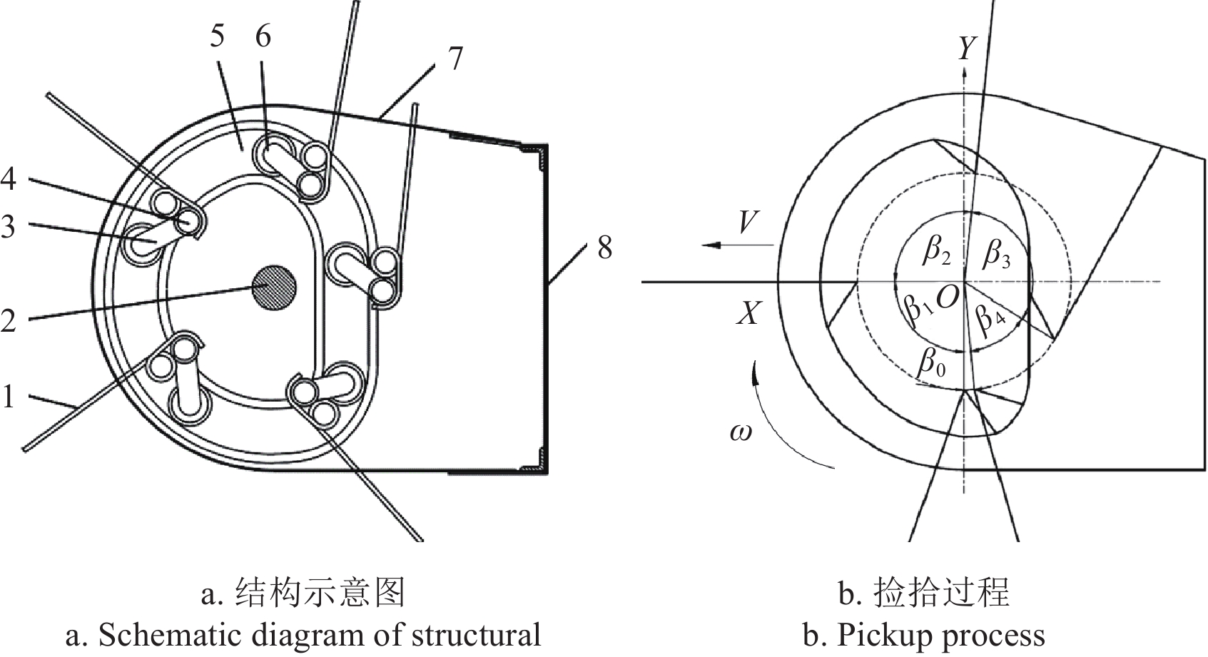
![]()
图 1 弹齿滚筒捡拾结构与捡拾过程示意图
1.弹齿2.中心轴3.曲柄4.弹齿轴5.凸轮滑道6.滚轮 7.护板8.后侧板1. Spring teeth 2. Shaft 3. Crank 4. Tine shaft 5. Cam slide 6. Contact roller 7. Guard board 8. Rear side panel注:β1~β4为弹齿捡拾、举升、推送和空回阶段的工位角,rad;V为捡拾装置水平移动速度,m·s-1;ω为滚筒转动角速度,rad·s-1。Note:β1-β4 are the station angle for pickup, lifting, pushing, and empty return stages of spring teeth, rad;V is the horizontal speed of the pickup device,m·s-1;ω is rotational angular speed of the cylinder,rad·s-1.
Figure 1. Structure and pickup process diagram of spring-finger cylinder picker
![]()
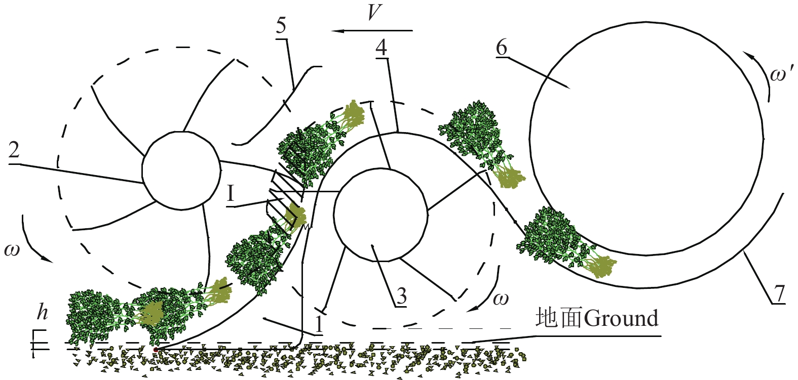
图 2 铲齿-双滚筒捡拾原理
1.铲齿 2.拨秧滚 3.捡拾滚 4.护板 5.挡秧齿 6.搅龙 7.筛板1.Shovel teeth 2. Pushing cylinder 3. Picking cylinder 4. Shield 5. Seedling blocking teeth 6. Spiral conveyor 7. Sieve plate注:ω′为搅龙转动角速度,rad·s−1;h为铲齿入土深度,mm;Ⅰ为拨秧滚与捡拾滚重合区域。Note:ω′ is rotational angular speed of the auger,rad·s−1;h is the depth of shovel teeth into soil,mm;Ⅰ is the overlapping area of pushing cylinder and picking cylinder.
Figure 2. Shovel teeth - two cylinders peanut pickup principle
![]()
图 3 铲齿-双滚筒捡拾机构结构简图
1.铲齿2.拨秧滚 3.捡拾滚 4.护板 5.挡秧齿
Figure 3. Pickup device structure diagram
1.Shovel teeth 2. Pushing cylinder 3. Picking cylinder 4. Shield 5. Seedling blocking teeth
![]()
图 4 花生植株受力图
注:F1为地面与花生条铺对质点P的作用力,N;G为P的重力,N;Fm1为P的向心力,N;Ff1为铲齿对花生植株的摩擦力,N;N1为铲齿对花生植株支持力,N;α0为铲齿入土角,(°);α为P所在铲齿上切线与水平方向的夹角,(°)。
Figure 4. Stress diagram of peanut plant
Note:F1 is the force of ground and peanut strips on mass point P,N;G is the gravity of P,N;Fm1 is the centripetal force of P,N;Ff1 is the friction force of shovel teeth on peanut plants,N;N1 is the support of shovel teeth on peanut plants,N;α0 is oil angle of shovel teeth,(°);α is the angle between the tangent and the horizontal direction of P on the shovel teeth ,(°).
![]()
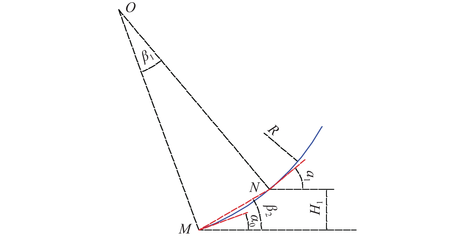
图 6 铲齿入土时刻的几何关系图
注:α1为N点铲齿切线与水平方向的夹角,(°);H1为拨秧齿最小离地间隙,mm;β1为圆弧MN对应的圆心角,(°);β2为直线MN与水平面的夹角,(°);R为铲齿半径,mm。
Figure 6. Geometric relationship diagram at moment of shovel teeth into soil
Note:α1 is the angle between the tangent line of the N-point shovel tooth and the horizontal direction,(°);H1 is the minimum ground clearance of pushing teeth,mm;β1 is the entral angle of arc MN,(°);β2 is the angle between MN and horizontal plane,(°);R is shovel teeth radius,mm.
![]()
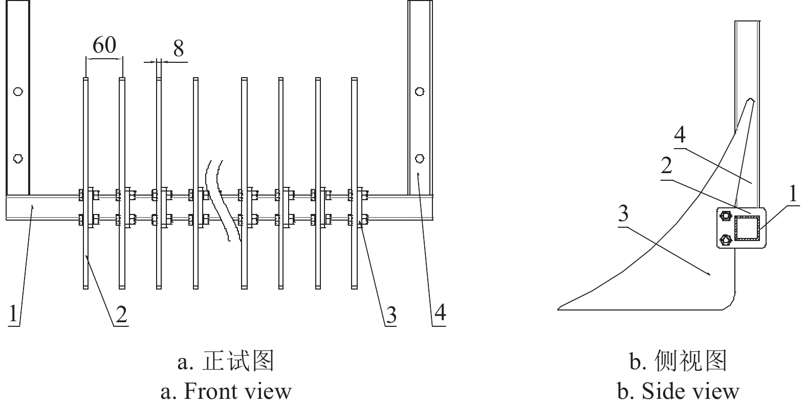
图 7 铲齿结构示意图
1.铲齿架 2.安装板 3.铲齿片4.侧板
Figure 7. Structural diagram of shovel
1. Shovel teeth rack 2. Installation plate 3. Shovel teeth 4. Side plate
![]()
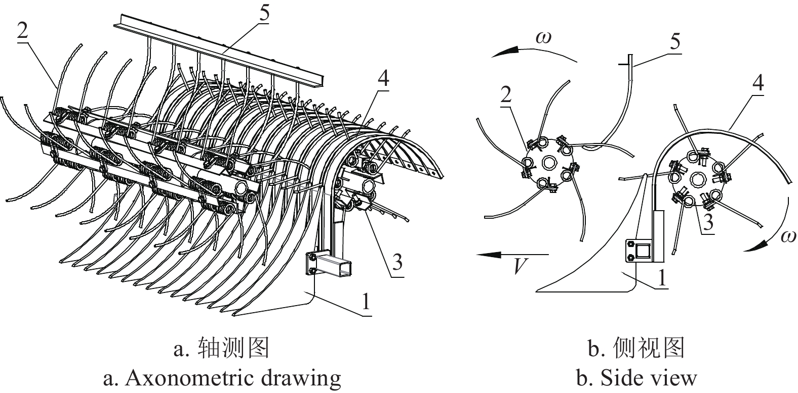
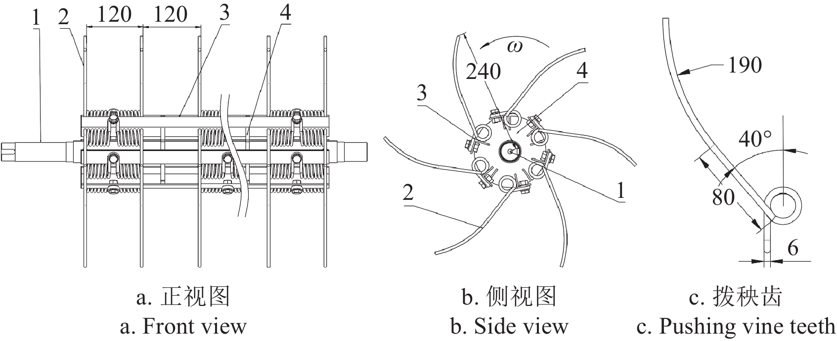
图 8 拨秧滚与拨秧齿结构图
1.拨秧滚轴 2.拨秧齿 3.拨秧齿杆 4.辐轮盘
Figure 8. Structural diagram of pushing cylinder and pushing teeth
1. Pushing cylinder shaft 2. Pushing teeth 3. Pushing teethed rod 4. Spoke disc
![]()
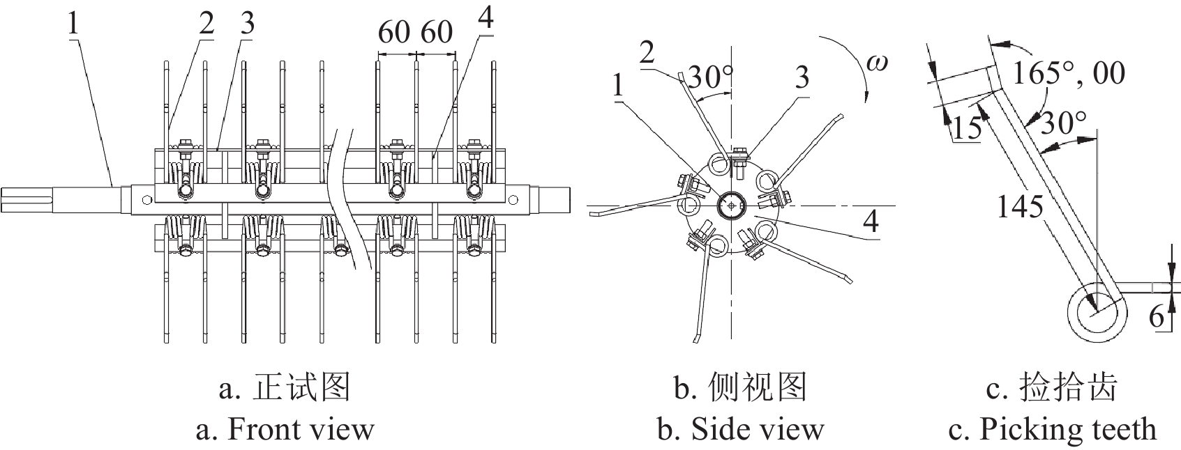
图 9 捡拾滚与捡拾齿结构图
1.捡拾滚轴 2.捡拾齿 3.捡拾齿杆 4.辐轮盘
Figure 9. Structural diagram of picking cylinder and picking teeth
1. Picking cylinder shaft 2.Picking teeth 3.Picking teethed rod 4. Spoke disc
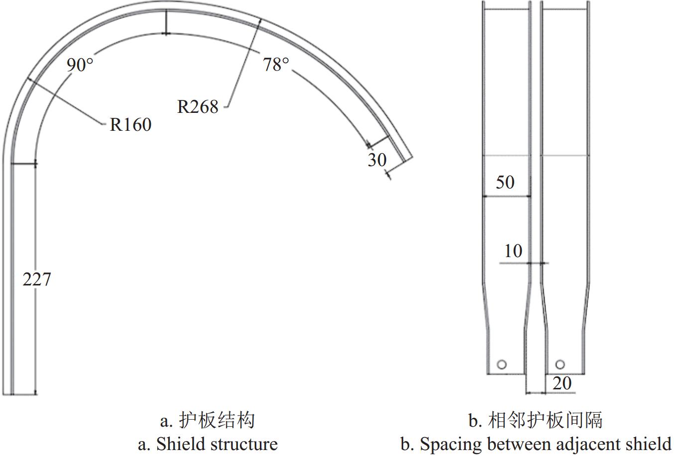
![]()
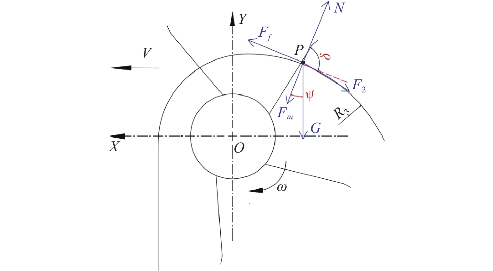
图 10 推送阶段花生植株受力分析
注:F2为捡拾齿对质点P的作用力,N;Fm为P绕护板转动的向心力,N;N为护板对P的支持力,N;Ff为护板对P的摩擦力,N;ψ为Fm与竖直方向的夹角,(°);δ为捡拾齿与护板夹角,(°);R3为护板半径,mm。
Figure 10. Diagram of peanut plant stress analysis in pushing process
Note:F2 is the force of picking teeth on mass point P,N;Fm is the centripetal force of P rotating around the shield,N;N is the support of the shield for P,N;Ff is the friction force between the shield and P,N;ψ is the angle between Fm and the vertical direction,(°);δ is the angle between picking teeth and shield,(°);R3 is the radius of shield.
![]()
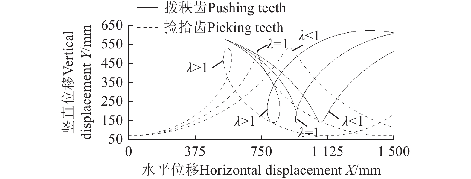
图 12 捡拾齿和拨秧齿在不同捡拾速比下的运动轨迹
Figure 12. Motion locus of picking teeth and pushing teeth under different ratio of picking cylinder speed to forward speed λ
![]()
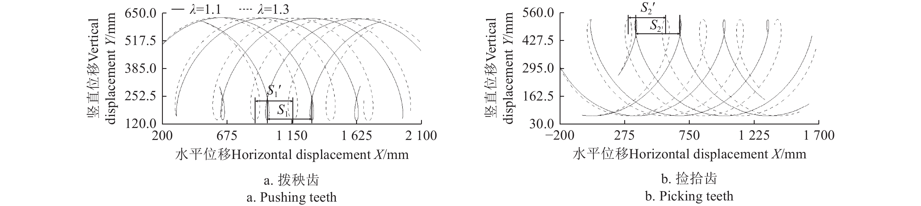
图 13 四排拨秧齿与捡拾齿运动轨迹
注:S1、S2分别为λ=1.1时的拨秧齿和捡拾齿节距,mm;S1'、S2'分别为λ=1.3时的拨秧齿和捡拾齿节距,mm。
Figure 13. Motion locus of four rows of pushing teeth and picking teeth with different rows
Note:S1, S2 is the pitch of the pushing teeth and picking teeth when λ=1.1,repectively, mm;S1' , S2' is the pitch of the pushing teeth and picking teeth when λ=1.3,respectively, mm.
表 1 不同排数的拨秧齿与捡拾齿节距
Table 1 Pitch between different rows of pushing teeth and picking teeth
mm 项目Items λ 齿排数Number of teeth rows n 4 5 6 拨秧齿
Pushing teeth1.1 324.7 274.2 228.5 1.3 290.0 232.0 193.3 捡拾齿
Picking teeth1.1 328.4 263.7 219.0 1.3 278.0 222.3 185.3  下载: 导出CSV
表 2 试验因素与水平
Table 2 Factors and levels of experiment
水平
Level前进速度
Forward speed A/(m·s−1)捡拾速比
Pickup speed ratio B铲齿半径
Shovel teeth radius C/mm-1 0.9 1.1 450 0 1.2 1.2 500 1 1.5 1.3 550
下载: 导出CSV
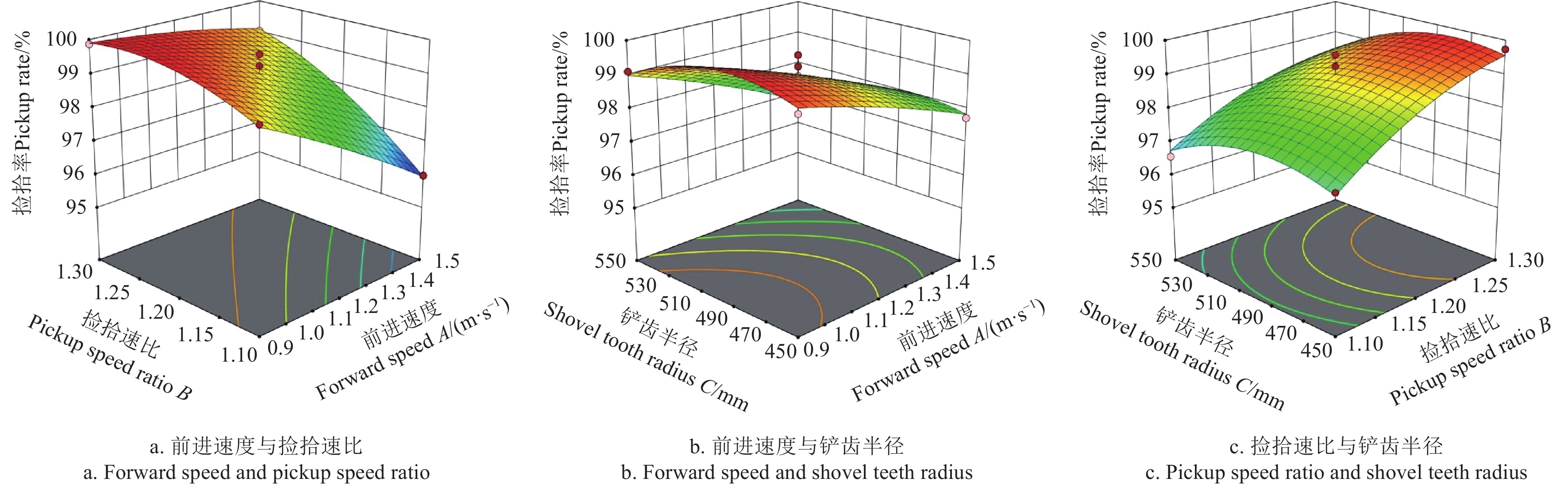
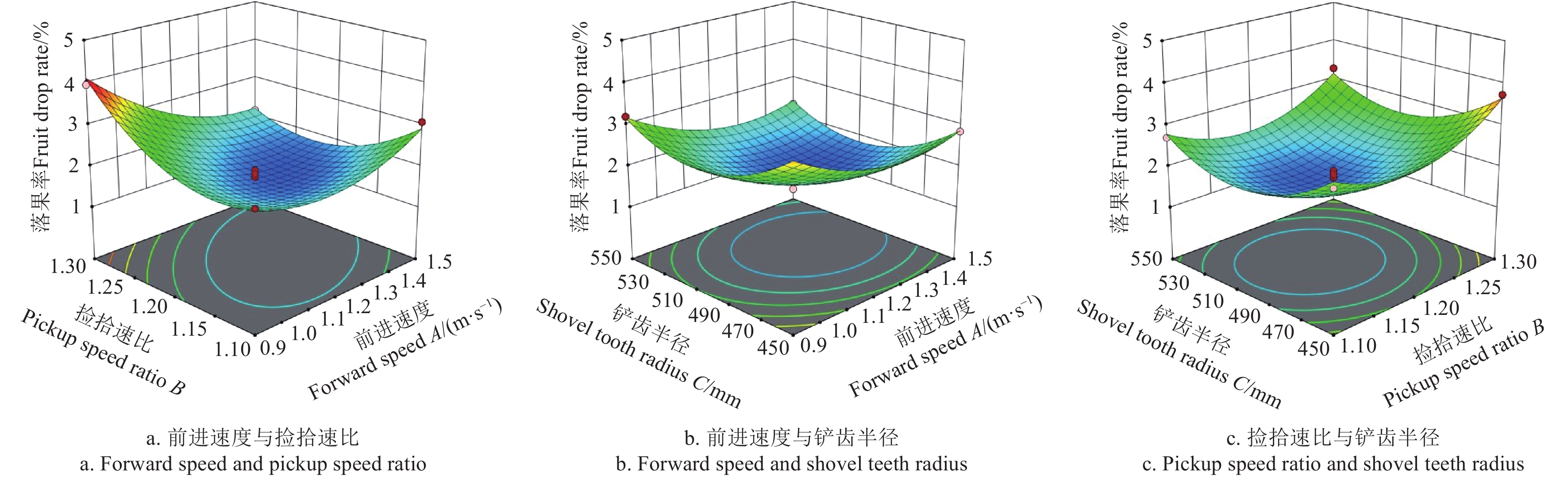
表 3 试验方案与试验结果
Table 3 Test plan and results
序号
Serial No.A/( m·s−1) B C/mm 捡拾率
Pickup rate J/%落果率
Fruit drop rate L/%1 0.9 1.1 500 99.12 2.52 2 1.5 1.1 500 95.98 3.08 3 0.9 1.3 500 99.87 3.96 4 1.5 1.3 500 99.04 2.14 5 0.9 1.2 450 99.41 3.62 6 1.5 1.2 450 97.74 2.85 7 0.9 1.2 550 99.10 3.21 8 1.5 1.2 550 96.94 2.31 9 1.2 1.1 450 97.35 2.96 10 1.2 1.3 450 99.74 3.74 11 1.2 1.1 550 96.57 2.71 12 1.2 1.3 550 98.38 3.28 13 1.2 1.2 500 99.25 1.73 14 1.2 1.2 500 98.73 1.91 15 1.2 1.2 500 98.57 1.61 16 1.2 1.2 500 98.97 1.82 17 1.2 1.2 500 99.58 1.44
下载: 导出CSV
表 4 验证试验数据
Table 4 Verify experimental data
试验号Test number 捡拾率Pickup rate J/% 落果率Pod loss rate L/% 1 99.43 1.95 2 98.96 1.74 3 99.15 1.88 4 99.26 1.78 5 99.30 1.85 平均值
Mean value99.22 1.84
下载: 导出CSV
-
[1] 中华人民共和国国家统计局. 中国统计年鉴[M]. 北京:中国统计出版社,2022. [2] United States Department of Agriculture Foreign Agricultural Service. Overview of world peanut production[EB/OL]. (2022-11)[2022-11-24]. https://apps.fas.usda.gov/psdonline/app/index.html#/app/advQuery.
[3] 陈中玉,高连兴,Charles Chen,等. 中美花生收获机械化技术现状与发展分析[J]. 农业机械学报,2017,48(4):1-21. doi: 10.6041/j.issn.1000-1298.2017.04.001 CHEN Zhongyu, GAO Lianxing, Charles Chen, et al. Analysis on technology status and development of peanut harvest mechanization of China and the United States[J]. Transaction of the Chinese Society for Agricultural Machinery, 2017, 48(4): 1-21. (in Chinese with English abstract) doi: 10.6041/j.issn.1000-1298.2017.04.001
[4] 关萌,沈永哲,高连兴,等. 花生起挖晾晒后的果柄机械特性[J]. 农业工程学报,2014,30(2):87-93. GUAN Meng, SHEN Yongzhe, GAO Lianxing, et al. Mechanical properties of peanut peg after digging and drying[J]. Transactions of the Chinese Society of Agricultural Engineering (Transactions of the CSAE), 2014, 30(2): 87-93. (in Chinese with English abstract)
[5] 王冰,胡志超,彭宝良,等. 半喂入四行花生联合收获机弹指筛结构运行参数优化[J]. 农业工程学报,2017,33(21):20-28. doi: 10.11975/j.issn.1002-6819.2017.21.002 WANG Bing, HU Zhichao, PENG Baoliang, et al. Structure operation parameter optimization for elastic steel pole oscillating screen of semi-feeding four rows peanut combine harvester[J]. Transactions of the Chinese Society of Agricultural Engineering (Transactions of the CSAE), 2017, 33(21): 20-28. (in Chinese with English abstract) doi: 10.11975/j.issn.1002-6819.2017.21.002
[6] 高连兴,刘维维,王得伟,等. 典型花生收获工艺流程及相关机械术语研究[J]. 花生学报,2014,43(3):26-30. doi: 10.3969/j.issn.1002-4093.2014.03.007 GAO Lianxing, LIU Weiwei, WANG Dewei, et al. Typical technological processes and machine concepts of peanut harvesting in China[J]. Journal of Peanut Science, 2014, 43(3): 26-30. (in Chinese with English abstract) doi: 10.3969/j.issn.1002-4093.2014.03.007
[7] 王东伟,尚书旗,赵大军,等. 4HBL-4型二垄四行半喂入自走式花生联合收获机[J]. 农业机械学报,2013,44(10):86-92. doi: 10.6041/j.issn.1000-1298.2013.10.015 WANG Dongwei, SHANG Shuqi, ZHAO Dajun, et al. Type-4HBL-4 two-ridges and four-lines semi-feeding self-propelled peanut combine harvester[J]. Transaction of the Chinese Society for Agricultural Machinery, 2013, 44(10): 86-92. (in Chinese with English abstract) doi: 10.6041/j.issn.1000-1298.2013.10.015
[8] 于昭洋,胡志超,曹明珠,等. 切流式花生全喂入联合收获机清选机构设计[J]. 农业工程学报,2019,35(9):29-37. doi: 10.11975/j.issn.1002-6819.2019.09.004 YU Zhaoyang, HU Zhichao, CAO Mingzhou, et al. Design of cleaning device of tangential flow and whole-feed peanut combine harvester[J]. Transactions of the Chinese Society of Agricultural Engineering (Transactions of the CSAE), 2019, 35(9): 29-37. (in Chinese with English abstract) doi: 10.11975/j.issn.1002-6819.2019.09.004
[9] 高连兴,陈中玉,Charles Chen,等. 美国花生收获机械化技术衍变历程及对中国的启示[J]. 农业工程学报,2017,33(12):1-9. GAO Lianxing, CHEN Zhongyu, Charles CHEN, et al. Development course of peanut harvest mechanization technology of the United States and enlightenment to China[J]. Transactions of the Chinese Society of Agricultural Engineering (Transactions of the CSAE), 2017, 33(12): 1-9. (in Chinese with English abstract)
[10] 许涛,刘志侠,高连兴,等. 中美花生捡拾技术研究现状与发展分析[J]. 沈阳农业大学学报,2023,54(3):372-384 doi: 10.3969/j.issn.1000-1700.2023.03.013 XU Tao, LIU Zhixia, GAO Lianxing, et al. Technology research status and development of peanut pickup device of China and the United States[J]. Journal of Shenyang Agricultural University, 2023, 54(3): 372-384. (in Chinese with English abstract) doi: 10.3969/j.issn.1000-1700.2023.03.013
[11] 许涛,沈永哲,高连兴,等. 基于两段收获的弹齿式花生捡拾机构研究[J]. 农业机械学报,2016,47(3):90-97,111. doi: 10.6041/j.issn.1000-1298.2016.03.013 XU Tao, SHEN Yongzhe, GAO Lianxing, et al. Spring-finger peanut pickup mechanism based on two-stage harvest[J]. Transaction of the Chinese Society for Agricultural Machinery, 2016, 47(3): 90-97,111. (in Chinese with English abstract) doi: 10.6041/j.issn.1000-1298.2016.03.013
[12] 许涛,高连兴,刘志侠. 一种铲齿-齿滚组合式花生捡拾装置:CN112400477B[P].2022-06-07. [13] 许涛,高连兴,刘志侠. 铲齿-弹齿滚筒组合式花生捡拾装置:CN112400478B[P].2022-06-07. [14] 许涛,高连兴. 一种椭圆行星轮系式弹齿滚筒花生捡拾装置:CN112833141B[P].2023-05-12. [15] 王申莹,胡志超,徐弘博,等. 全喂入式花生捡拾收获机捡拾输送装置研制[J]. 农业工程学报,2019,35(19):20-28. doi: 10.11975/j.issn.1002-6819.2019.19.003 WANG Shenying, HU Zhichao, XU Hongbo, et al. Design and test of pickup and conveyor device for full-feeding peanut pickup harvester[J]. Transactions of the Chinese Society of Agricultural Engineering (Transactions of the CSAE), 2019, 35(19): 20-28. (in Chinese with English abstract) doi: 10.11975/j.issn.1002-6819.2019.19.003
[16] 王伯凯,顾峰玮,于昭洋,等. 轴流式全喂入花生收获机捡拾机构设计与试验[J]. 农业机械学报,2020,51(10):132-141,169. doi: 10.6041/j.issn.1000-1298.2020.10.015 WANG Bokai, GU Fengwei, YU Zhaoyang, et al. Design and experiment of picking-up mechanism of axial-flow full-feed peanut harvester[J]. Transaction of the Chinese Society for Agricultural Machinery, 2020, 51(10): 132-141,169. (in Chinese with English abstract) doi: 10.6041/j.issn.1000-1298.2020.10.015
[17] 胥南,王东伟,尚书旗,等. 花生捡拾联合收获机捡拾装置优化设计与运动学分析[J]. 农机化研究,2021,43(12):128-132. doi: 10.3969/j.issn.1003-188X.2021.12.023 XU Nan, WANG Dongwei, SHANG Shuqi, et al. The optimum design and kinematics analysis of the picking device of peanut combine harvester[J]. Agricultural Mechanization Research, 2021, 43(12): 128-132. (in Chinese with English abstract) doi: 10.3969/j.issn.1003-188X.2021.12.023
[18] 陈有庆,胡志超,王申莹,等. 割秧后花生收获机捡拾装置设计与试验[J]. 农业工程学报,2020,36(16):1-8. doi: 10.11975/j.issn.1002-6819.2020.16.001 CHEN Youqing, HU Zhichao, WANG Shenying, et al. Design and experiments of pickup device of peanut harvester after cutting peanut straws[J]. Transactions of the Chinese Society of Agricultural Engineering (Transactions of the CSAE), 2020, 36(16): 1-8. (in Chinese with English abstract) doi: 10.11975/j.issn.1002-6819.2020.16.001
[19] 高连兴,许涛,沈永哲,等. 一种弹齿滚筒式花生捡拾装置:CN105638068B[P].2018-07-03. [20] 梁港平,高连兴,周泉,等. 一种搂齿式花生捡拾摘果装置:CN216820716U[P].2022-06-28. [21] 高连兴,陆荣,刘明国等. 一种直立锥滚筒式花生脱壳机:CN109984345A[P].2019-07-09. [22] 田连祥,尚书旗,王东伟,等. 4HT-2花生条铺收获机的研制与试验[J]. 农机化研究,2018,40(7):87-91. doi: 10.3969/j.issn.1003-188X.2018.07.016 TIAN Lianxiang, SHANG Shuqi, WANG Dongwei, et al. Development and experiment of type 4HT -2 peanut harvester[J]. Agricultural Mechanization Research, 2018, 40(7): 87-91. (in Chinese with English abstract) doi: 10.3969/j.issn.1003-188X.2018.07.016
[23] 王东伟,尚书旗,韩坤. 4HJL-2型花生捡拾摘果联合收获机的设计与试验[J]. 农业工程学报,2013,29(11):27-36,294. WANG Dongwei, SHANG Shuqi, HAN Kun. Design and test of 4HJL-2 harvester for peanut picking-up and fruit-picking[J]. Transactions of the Chinese Society of Agricultural Engineering (Transactions of the CSAE), 2013, 29(11): 27-36,294. (in Chinese with English abstract)
[24] 王伯凯,胡志超,曹明珠,等. 轴流式花生捡拾收获机设计与试验[J]. 农业机械学报,2021,52(1):109-118,98. WANG Bokai, HU Zhichao, CAO Mingzhu, et al. Design and test of axial-flow peanut picking and harvesting machine[J]. Transaction of the Chinese Society for Agricultural Machinery, 2021, 52(1): 109-118,98. (in Chinese with English abstract)
[25] 王文明,王春光. 弹齿滚筒式捡拾装置参数分析与仿真[J]. 农业机械学报,2012,43(10):82-89. doi: 10.6041/j.issn.1000-1298.2012.10.015 WANG Wenming, WANG Chunguang. Parameter analysis and simulation of spring-finger cylinder pickup collector[J]. Transaction of the Chinese Society for Agricultural Machinery, 2012, 43(10): 82-89. (in Chinese with English abstract) doi: 10.6041/j.issn.1000-1298.2012.10.015
[26] 乌吉斯古楞,刘伟峰,包那日那. 滚筒式捡拾器的运动仿真[J]. 农机化研究,2010,32(9):50-53. Wujisiguleng, LIU Weifeng, Baonarina. Simulation of spring-teeth pick-up[J]. Agricultural Mechanization Research. 2010, 32(9): 50-53. (in Chinese with English abstract)
[27] 王国权,余群,卜云龙,等. 秸秆捡拾打捆机设计及捡拾器的动力学仿真[J]. 农业机械学报,2001,32(5):59-61,68. doi: 10.3969/j.issn.1000-1298.2001.05.019 WANG Guoquan, YU Qun, BU Yunlong, et al. Design of pickup baler and dynamic simulation of pickup roller[J]. Transaction of the Chinese Society for Agricultural Machinery, 2001, 32(5): 59-61,68. (in Chinese with English abstract) doi: 10.3969/j.issn.1000-1298.2001.05.019
[28] 中华人民共和国农业部. 花生收获机械 作业质量:NY/T 502—2016[S]. 北京:中国标准出版社,2016. [29] 中华人民共和国农业部. 花生收获机械 质量评价技术规范:NY/T 2204—2012[S]. 北京:中共农业出版社,2013. [30] 潘丽军,陈锦权. 试验设计与数据处理[M]. 南京:东南大学出版社,2008. [31] 王永菲,王成国. 响应面法的理论与应用[J]. 中央民族大学学报(自然科学版),2005(3):236-240. doi: 10.3969/j.issn.1005-8036.2005.03.008 WANG Yongfei, WANG Chenguo. The application of response surface methodology[J]. Journal of the CUN(Natural Sciences Edition), 2005(3): 236-240. (in Chinese with English abstract) doi: 10.3969/j.issn.1005-8036.2005.03.008
-
期刊类型引用(1)
1. 郭佩杰,陈雨,陈宇翔,汪海英,肖爱萍,陈军,钟培林. 液态粪肥施肥机肥罐防浪板的设计与试验. 农业工程学报. 2025(02): 47-57 .  本站查看
本站查看
其他类型引用(0)


计量
- 文章访问数: 259
- HTML全文浏览量: 44
- PDF下载量: 140
- 被引次数: 1