Design and test of the intra-row electric driven obstacle avoidance weeder for wolfberry
-
摘要:
针对现有枸杞株间除草机结构复杂、作业效率不高等问题,该研究设计了一种株间电驱动避障除草机。通过对除草机工作原理的分析,确定了关键组件及其参数,包括整机起降机构、信号采集机构、自动避障机构和除草刀盘等。确定自动避障控制系统设计方案,进行闭环控制系统的硬件选型与软件设计,对控制程序进行PID(proportion-integral-differential,比例-积分-微分)参数整定。利用ADAMS创建除草机虚拟样机模型,通过单因素仿真试验,确定了前进速度、除草刀盘转速和信息采集传感器预设角度阈值为主要影响因素。设计并进行了二次回归组合试验,以除草率作为评估指标,通过试验建立除草率的回归模型,得到最优参数配置为:前进速度300 mm/s,除草刀盘转速300 r/min,预设角度阈值10°。田间验证试验在最优参数设置下得到平均除草率91.24%,验证了模型预测的准确性。结果可为枸杞及类似作物株间除草机设计及其工作原理研究提供科学依据。
Abstract:Weeds as co-occurring vegetation have posed significantly impacts on the growth and yield of wolfberry during cultivation. As such, effective weed management is critical to the wolfberry orchard maintenance. However, most currently available hydraulic drives can lead to the complex structures and substantial weight in the existing intra-row weeding machines. The maneuverability of the equipment can also be constrained to increase manufacturing complexity and cost, leading to the low operational efficiency. In this study, an intra-row electric electric-driven weeder was designed with for obstacle avoidance. The weeder consisted of a frame, the take-off and landing mechanism, transmission, weeding, obstacle avoidance, and power supply. The frame served as the overall installation carrier for obstacle avoidance and weed removal machines. The weeding device mainly consisted of a DC motor module, chain transmission, and weeding cutter. The DC motor module was provided the power for the rotation of the weeding cutter through a chain drive. The automatic obstacle avoidance device was composed of a signal acquisition mechanism, servo motor modules, and a four-bar mechanism. The weeder was powered by an external 24V DC generator and a battery pack. The automatic obstacle avoidance control system consisted of signal acquisition, monitoring feedback, program control, and a servo motor module. The signal acquisition was used to obtain the accurate position information of wolfberry in real-time, and then transmitted into the program control section. The theoretical driving signal was then calculated to dynamically control the speed and rotation angle of the servo motor module. The monitoring feedback section was used to determine the deviation that generated by the contact between the contact rod and wolfberry plants. The difference between the preset deviation threshold was monitored in real time. The feedback information was then transmitted to the program control section, which was compared with the theoretical driving signal of the servo motor module, and then precisely adjusted the actual obstacle avoidance. Furthermore, the hardware selection and software design of the closed-loop control system were carried out on the control system of automatic obstacle avoidance. The PID (proportion-integral-differential) parameters of the control program were adjusted at the operating speed of 400 mm/s. The optimal combination of PID parameters was achieved: KP=56.00, Ki=0.006, and Kd=34.74. A virtual prototype model of weeder was established using ADAMS software. Kinematic simulations were then executed to verify the alignment between the simulated trajectory and theoretical predictions of the weeding cutter. Subsequently, single-factor simulations were performed on ADAMS, taking the weeding coverage rate as the assessment criterion. The main influencing factors were then determined, including operating speed, rotation speed of the weeding cutter, and preset angle threshold of information collection sensors. Taking the three main influencing factors obtained from the simulation as experimental factors, and the weed control rate as an evaluation index, a quadratic regression combination experiment was designed to construct a regression model of the weed control rate. Design Expert 8.0.6 software was utilized to optimize the parameters of the regression model. The optimal parameters were obtained as follows: operating speed of 300 mm/s, rotation speed of the weeding cutter of 300 r/min, and preset angle threshold of 10°. The field validation experiment was obtained an average weed control rate of 91.24% under the optimal parameter settings, indicating the high accuracy of the model. This finding can provide a scientific basis to optimize the parameters of intra-row weeding machines for wolfberry and similar crops.
-
0. 引 言
溶解氧水平[1-2]是评估水质的关键指标之一,对溶解氧的实时监测和有效调控对于保障水产养殖经济和水产品质量具有至关重要的意义。传统的溶解氧传感器价格昂贵、维护成本高,且外壳坚硬、体积较大、使用场景单一。新型应用场景的涌现对溶解氧测量提出了更广泛的需求和更高的要求。例如,在水产养殖中,贴合性较好的溶解氧传感器可以更方便地用于养殖鱼类习性[3]的相关研究,反映鱼类活动对溶解氧浓度的倾向[4],同时可以根据鱼类活动范围来了解养殖环境中溶解氧的分布情况[5-6]以进行针对性增氧,或贴合水下软体机器人进行水质监测[7]等,这些场景对溶解氧传感器提出了体积小、重量轻、可弯曲、生物相容等要求[8-9]。柔性传感器的发展为应对以上挑战提供了新的思路。
柔性溶解氧传感器制备的关键在于制造工艺、材料选择和结构设计。2003年,MITSUBAYASHI等[10]采用光刻和溅射技术在透氧膜FEP(fluorinated ethylene propylene,全氟乙烯丙烯共聚物)薄膜上制作两电极,通过热封技术将KCL电解液和电极封装在透氧膜与非渗透性膜之间,制备了5 cm×1.5 cm的柔性溶解氧传感器,并经过试验验证电极可以穿戴于人体前臂皮肤进行皮痒浓度测量。2005年,该团队对传感器进行结构改进,成功将传感器贴附在大白兔的结膜上监测结膜中的动脉氧压。2016年,MOYA等[11]采用喷墨打印技术取代繁琐的微纳加工技术,成功制作出一款具有良好结构和微观形态的三电极溶解氧传感器,以较低的成本和简化的工艺流程实现了高性能传感器制备(R2>0.97),尽管该传感器未进行完整封装,但其表现已经充分证明了喷墨打印技术在微型传感器,尤其是微型溶解氧传感器制造领域的应用潜力。2019年,SHE等[12]通过电子束蒸发技术和光刻技术将电极图案化沉积在PI(polyimide,聚酰亚胺)薄膜上,并用同样的工艺沉积铬(Cr)以改善电极与聚酰亚胺基板之间的黏附性,利用PDMS(polydimethylsiloxane,聚二甲基硅氧烷)构建厚膜腔体并注入NaCl溶液,采用PDMS薄膜作透氧膜,得到一款稳定性好(14d 内响应特性无明显变化)、线性程度高(R2>0.99)的传感器,这款传感器可用于生物医学植入,比如监测啮齿动物股骨缺损模型中骨再生过程中的氧张力。2017年,LUO等[13]利用低温共烧陶瓷技术(low temperature co-fired ceramic,LTCC)和丝网印刷技术制造了一种多层结构的克拉克型溶解氧传感器,该传感器以PDMS作透氧膜,内部包含KCL电解液和检测流道,为微流控式溶解氧检测芯片制作提供了方案,可以用于生物制药过程中的溶解氧检测。2018年,OBEIDAT等[14]基于丝网印刷电极和Nafion(全氟磺酸型聚合物)溶液制备了三电极溶解氧传感器,用于分析马和牛的卵母细胞和胚胎细胞中的线粒体功能,以更好地确定它们的质量和活力以及胚胎细胞的发育情况。阵列传感器的优势在于传感元件的数量较多、传感数值较为准确,LEE等[15]在2017年研发了一款一次性阵列式溶解氧传感器,每个电极单元都被二氧化硅薄膜覆盖形成单独的腔体,利用施加在电极阴极和阳极之间的电压电解水产生气泡,打破稀薄的二氧化硅薄膜使待测水体流入腔体,每次打开一个腔体进行水体溶解氧监测。随着时间流逝当水中的漂浮物或污染物黏附在固体电解质的表面时,就会放弃这个腔体而打开下一个腔体进行接力式测量,以此完成长期测量的任务。鉴于数量多、不怕污染的特性,传感器创新性地采用无透氧膜的形式,可较为方便地用于污水检测。然而,这些柔性溶解氧传感器大多存在制造条件要求高、流程复杂的问题,且测量参数单一、需配合其他传感器进行补偿矫正,无成熟的传感系统,目前相关研究仍处于原型开发阶段[16-21]。
因此,研发高性能、低成本、微体积、具备补偿能力、生产环境友好的柔性溶解氧智能传感器具有重要意义。在传感器制备的微细加工工艺中,磁控溅射[22]工艺具有沉积速率快、沉积温度低,镀膜面积大、均匀性好、膜基结合力强的优点,且该工艺环保无污染,易于操控,对基材要求较低,可用于工业规模的生产。点胶喷墨[23]工艺具有精确控制、节约材料,提高生产效率和精度的优点。两种工艺均具有较好的综合性能,能满足大多数柔性传感器制备的要求。
综上,本研究将采用磁控溅射和点胶喷墨工艺,提出一种集成温度传感器的柔性溶解氧传感器,系统测试柔性传感器的传感、机械弯曲等性能,并开发传感电路和智能处理系统,通过采集传感器数据自动进行溶解氧传感器的温度补偿和传感器传输数据,实现便携、多功能的溶解氧测量,以期推动柔性溶解氧智能传感器在渔业应用中的可行性和实用性。
1. 材料与方法
1.1 传感原理
在极谱式溶解氧检测过程中[24],通过对传感器电极施加极化电压,促使溶解氧在电极表面发生氧还原反应,并以反应的电流大小来检测溶解氧浓度。具体地,施加电压会使传感器电极表面形成电势差,使得电极表面的电子能级降低,当氧气分子接近电极表面时,会捕获电极表面的电子并发生还原反应,反应过程中电子的流动形成了电流,通过测量该电流信号的大小可以确定溶解氧的浓度[25-26]。本研究的溶解氧传感器采用极谱式三电极结构,传感器结构及反应原理如图1所示,传感器选用金电极作工作电极和辅助电极,Ag/AgCl电极作参比电极,并采用透氧膜封装KCL电解液与电极。三电极结构较两电极结构的优势在于:加入参比电极后,参比电极一方面用于维持恒定的极化电压,提高测量的准确性和稳定性;另一方面使得溶解氧检测中的反应原理发生变化,弥补了辅助电极和电解液消耗的问题,延长了传感器的寿命,此外,反应也不再消耗待测溶液中的氧气,从而使测量结果更加准确。反应原理[27]如下:
工作电极:
O2+2H++2e−→H2O2 (1) H2O2+2H++2e−→2H2O (2) 辅助电极:
2H2O→O2+4H++4e− (3) 聚(3,4-乙烯二氧噻吩)-聚苯乙烯磺酸(Poly(3,4-ethylenedioxythiophene):poly(styrenesulfonate),PEDOT:PSS)[28]是一种导电聚合物,因其独特的电学性能和稳定性而被广泛研究用于温度传感器。具有较好的柔韧性和耐磨性,并且比同类金属产品有更强的抗疲劳性[29]。此外,由于具有特殊的电子结构和分子轨道特性,该聚合物还表现出与金属一样的高导电性。本研究中柔性温度传感器采用电阻式温度传感器原理,即传感器电阻随温度变化而线性变化。
1.2 传感器设计与制备
1.2.1 传感器结构设计
本研究设计的柔性溶解氧传感器采用平面电极结构,为保证工作电极和辅助电极之间形成良好回路,提高传感器的灵敏度,采用工作电极置于参比电极和辅助电极之间、辅助电极环绕在工作电极周围的平面布局方案,透氧膜封装电解液和平面电极等用垂直布局方案。
折线棱角可能会由于电场浓缩效应和局部电流密度变化较大而引发电荷尖端放电等边缘效应。因此,溶解氧电极反应区域的边缘均采用圆弧设计,从而降低局部电流密度的变化和不均匀性。溶解氧电极工作电极设计为圆形(直径为1.5 mm),辅助电极以同心圆弧方式环绕在工作电极周围,工作电极直径、辅助电极圆弧宽度、工作电极和辅助电极之间距离的比例为4:2:1。此外,为在有限的电极面积下增大传感结构与测量环境的接触面积[30],以便更加准确反映环境真实温度,温度传感器电极采用折线栅形结构,传感线条的宽度为0.25 mm,电极栅格间距为4 mm。
1.2.2 传感器制备方法
传感器制备流程如图2所示,首先通过磁控溅射仪(电流设定40 mA,时间设定120 s)在经过乙醇和UV清洗后的PI薄膜基底上制造温度传感器的金电极引脚,采用微电子打印机的点胶功能按照设计方案点胶SENS-T037墨水制备温度敏感层电极,通过120 ℃、30 min烧结去除多余有机溶剂,形成致密的导电层,最终取除气泡后的PDMS混合溶液(主剂与固化剂10:1)均匀刮涂在电极导电区域,在60 ℃下加热40 min,完成柔性温度传感器制备。
根据设计的电极图案,采用激光雕刻机刻制掩膜并紧密贴合PI基底的另一面,放置在磁控溅射仪中连续进行4次溅射以得到具备良好电导率的电极。溅射完成后将金电极置于弱硫酸溶液中,采用循环伏安法(cyclic voltammetry,CV)对金电极进行活化清洗。
采用微电子打印机的点胶功能进行银电极的制备。通过实验确定了银电极制备的最佳工艺:点胶高度200 μm,点胶气压80 kPa,点胶速度2 mm/s,固化烧结条件为150 ℃下烧结30 min。取除气泡后的PDMS混合溶液(主剂与固化剂10:1)均匀刮涂在电极导电区域上,留出电极的反应区域,在60 ℃的真空加热箱中加热40 min,然后将电极置于0.1 M HCl溶液中,采用电化学工作站中的电流时间法(amperometric i-t curve,简称i-t)(200 mV,180 s恒电位扫描)将Ag电极进行氯化形成Ag/AgCL参比电极。
最终采用0.1 M KCl溶液作电解液,商用AZ8403透氧膜作透氧膜,硅胶作边缘封闭材料,完成溶解氧电极制备和封装,制备完成的传感器如图3a。
1.2.3 仪器与材料
试验所用的仪器有:柔性微电子打印机(DB100,上海众频科技有限公司,上海,中国),支持多种印刷和半导体工程。磁控离子溅射仪(CIS400P,上海众频科技有限公司,上海,中国),支持金靶材的薄膜溅射。激光打标机(TR-30W,山东途锐激光设备有限公司,山东,中国),支持金属、塑料、纸张等雕刻塑性。真空干燥箱(BZF-50,上海博迅医疗生物仪器股份有限公司,上海,中国),加热范围为室温~250 ℃。UV光清洗机(CCI250GF-TC,上海众濒科技有限公司,上海,中国),有效清洗面积256 mm×256 mm。电化学工作站(CHI660D,上海辰华仪器有限公司,上海,中国),支持多种电化学测量技术。连续变倍体显微镜(SMZ680,北京京百卓显科技有限公司,北京,中国),支持柔性传感器的微观表征。
试验所用的材料有:PI基底(0.015 mm×200 mm×148 mm,科之注电子科技重庆有限公司,重庆,中国)。导电银浆(KZ-R62,科之注电子科技重庆有限公司,重庆,中国)。温敏墨水(KZ-SENSE-102,科之注电子科技重庆有限公司,重庆,中国),主要成分为PEDOT:PSS。透氧膜(AZ8403,衡欣科技股份有限公司,台湾,中国)。主要试剂有氯化钾(KCL)溶液、硫酸(H2SO4)溶液、铁氰化钾(K3[Fe(CN)6])溶液、盐酸(HCL)溶液、聚二甲基硅氧烷(PDMS)溶液及其固化剂。
1.3 传感器参数测定
1.3.1 极化电压和极化时间
极谱式溶解氧传感器在标定和使用前有2个重要参数需要确定:极化电压和极化时间。
极化电压通过线性扫描伏安法(linear sweep voltammetry,LSV)测定。在20 ℃下溶解氧饱和的纯水中,在−0.8~0 V之间以100 mV/s的步长对柔性溶解氧传感器进行LSV测量,测量曲线如图3b,由图可知,氧还原的电流随着极化电压增大而增大,其中有一个明显的拐点,电流随电压的变化速率发生明显变化,将图像分为2个区域。测量结果符合溶解氧反应的LSV模型[19, 21]:
ii0=(1−ii1,c)e−αnfη−(1−ii1,a)e(1−α)nfη (4) 式中i0是交换电流,A;α 是转移系数;n是电子数;f为法拉第常数与理想气体常数和温度的比值;η为过电位,V;i1,c和i1,a分别是扩散抑制阴极电流和阳极电流。该方程描述了动力学控制区(图3b中区域1)和扩散控制区(区域2)。在低偏置电压水平下,工作电极上的反应处于动力学控制区域,电流对施加的电压有很强的依赖性。在较大电压偏置水平下,氧气输送到工作电极的过程从受动力学控制下转变为受扩散影响。
由LSV曲线可知,溶解氧反应的动力学控制范围约为−0.5~0 V的偏置电压下,而扩散控制区范围约为−0.7~−0.5 V,响应电流在该区域与溶解氧浓度成正比。因在不同溶解氧浓度的溶液中LSV曲线的扩散控制区略有波动,所以选取扩散控制区的中点电位−0.6 V作为极化电压。
极谱式溶解氧传感器的极化时间是指从施加极化电压开始到传感器稳定输出的工作状态的时间。试验测得所制备的溶解氧传感器的极化响应曲线如图3c,得知传感器极化时间为42 s。
1.3.2 温度补偿
温度是影响溶解氧测量的主要参数。随着温度升高,水中饱和溶解氧含量会降低,且电化学反应更加剧烈,需要通过实验进行补偿测试。在不同温度下测量溶解氧传感器在氧饱和环境和无氧环境下的输出值,用两点式拟合直线的方法得到不同温度下溶解氧含量与柔性溶解氧传感器采集电流的关系如图3d,由图可以看出,不同温度下传感器响应曲线的斜率相差较大,因此,对传感器进行温度补偿十分必要。
温度补偿的关键在于找出不同温度下溶解氧传感器响应曲线的斜率与温度之间的关系。由图3d得到斜率与温度的拟合曲线如图3e所示,曲线方程为:y=−
0.0676 x2−4.7784 x+88.59,R2=0.9995 。温度补偿的过程为:将图3e所示拟合曲线与溶解氧传感器所处温度对应后即可得出传感器响应曲线的斜率,进而计算得出如图3d的响应曲线,结合传感器电流大小从而得出溶解氧含量数值。1.4 智能传感系统搭建
智能传感器[31]具有信息处理、集成化设计、自动补偿和校准等功能。本研究根据所制备的三电极极谱式溶解氧传感器,搭建智能溶解氧检测系统:根据所制备传感器的信号输出范围、极化电压等参数设计相关电路模块,并结合三电极传感器的电学特性,用放大器构建三电极恒电位电路,为传感器提供准确的极化电压。根据传感器在不同温度下的线性拟合数据和温度补偿曲线,建立数据处理方法,使传感系统能够根据温度传感器采集数值自动选择溶解氧传感器在该温度下的响应曲线,结合溶解氧传感器采集的电流大小得出被测环境中的溶解氧含量,从而实现温度自动补偿校准、不同温度下溶解氧含量测量的功能。搭建完成的智能传感系统如图4所示,柔性传感器通过FPC(flexible printed circuit,柔性电路板) 排线与电路板连接,此外该智能传感系统可实现溶解氧和温度实时显示、蓝牙数据传输、有线数据传输等功能。
2. 结果与分析
2.1 光学显微结构表征结果
采用SMZ680连续变倍体显微镜对制备的柔性传感器进行微观表征,结果如图5所示。
如图5a所示,在高倍显微镜下,柔性温度传感器电极表面呈现细小致密且均质的紫黑色颗粒状材质,其主要成分是烧结后形成的PEDOT:PSS复合物晶体颗粒。
由图5b可以看出,柔性溶解氧传感器的金电极表面光滑平整,呈金色光泽,在显微镜灯光照射下均匀透亮,说明金电极具有均匀且较薄的厚度。磁控溅射金属薄膜的过程中存在边缘电场不均匀的现象,本研究在溅射的过程中,裁取的电极尺寸较小且放置于腔体中央因而获得了均匀平整的金电极。
图5c为Ag电极表面显微情况,可以看出电极粗细均匀、表面呈银色金属光泽,可以看到均质发光的亮点,具有良好的物理形态。图5d为Ag/AgCl参比电极的微观显示图,从图中可以看出Ag/AgCl电极表面呈现致密均匀的黑色颗粒,为Ag电极表面氯化形成的Ag/AgCl。
2.2 弯曲可靠性测试结果
采用柔性测试夹具对不同弯曲角度下传感器的性能进行测试:以溶解氧传感器向外弯曲为弯曲方向,在0°~60°内以15°为一个单位,在90°~180°内以30°为一个单位逐级增加弯曲度并测量每个角度下柔性温度传感器和柔性溶解氧传感器的数据,以确定传感器的可弯曲范围。测量结果分别如图6所示。
对于柔性温度传感器,其整体阻值随着弯曲度的增大而增大,弯曲角度在0°~60°时传感器阻值变化较小;当角度大于90°时,传感器阻值几乎呈线性增加;在180°时阻值比0°增加了14 kΩ,在结束形变的10 min后,阻值逐渐恢复到原始值附近,这得益于PEDOT:PSS分子链具有一定的弹性,可以在受到外力作用时发生形变,并在外力撤除后恢复原状,同时PEDOT:PSS中的导电聚合物网络在结束形变后可能会发生局部重组,重新建立导电路径,从而恢复到原来的电阻值。因此,柔性温度传感器正常使用的弯曲范围为0°~60°。
对于柔性溶解氧传感器,当弯曲角度小于45°时,传感器输出电流变化不大;当弯曲角度小于60°时,传感器输出电流随着角度逐渐增大,并且在弯曲形变结束后会逐渐恢复到原来的输出电流大小附近;而当角度到达90°时,传感器输出电流明显增大,且在恢复原来的形态后输出电流也比未弯曲时大。可知传感器表面因拉伸出现了肉眼未能识别的细小裂痕从而影响了传感器输出结果。因此能保持柔性溶解氧传感器正常使用的弯曲范围为0°~60°。
2.3 传感性能测试结果
2.3.1 溶解氧传感器
1)循环伏安法
循环伏安法测量溶液由1 M KCl和1 mM K3[Fe(CN)6]组成,不同扫描速率下的CV扫描曲线以及峰电流与扫描速度的平方根曲线如图7a和图7b所示。可以看出CV扫描曲线有明显的氧化峰和还原峰且氧化峰和还原峰,呈现较好的CV图像,峰电流与扫描速度的平方根之间两者具有较好的拟合度,即[Fe(CN)6]3−/4−在所制备的溶解氧传感器上的反应受扩散控制。
此外,图7a展示了采用制备的溶解氧传感器辅助电极pCE、参比电极pRE对比商用电极CE、RE进行CV扫描时扫描曲线的差别。使用所制备的pCE与商用CE之间几乎没有区别,而使用所制备的pRE对比商用RE时,两者CV图像形状一致,但电位产生了微小偏移,其原因在于[11]电极表面接触的氯化物的浓度差异:制备的参比电极pRE处于0.1 M KCl电解质溶液中,而商业参比电极RE处于3 M KCl的内部电解质溶液中。
2)静态特性
电化学工作站的电流时间法可以对电极施加极化电压并采集反应电流,利用该方法重复3次测得常温时柔性溶解氧传感器的输出值随溶解氧含量的拟合曲线如图7c,拟合方程y=−
0.0303 x−0.1327 ,R2达到0.9945 ,传感器灵敏度为−0.03 μA·L/mg,剩余电流大小为−0.1327 μA。溶解氧传感器漂移测试结果如图7d,溶解氧电极约在43s 附近完成极化,极化后电流处于相对稳定阶段,随着时间缓慢变大,最大电流差值为
0.0149 μA,在该温度下的对应溶解氧含量约为0.49 mg/L,传感器出现漂移的原因在于[12]:参比电极作为稳定的电势参考点,随着电流在其表面通过,促进了电极材质在溶液中发生物理降解,从而产生微小的电压漂移导致工作电极和对电极之间的电位差发生微小变化。3)动态特性
对同一溶液7天的溶解氧测量结果如图7e和图7f,可以看出传感器7 d 的响应曲线基本重合,在第7天 时达到最大偏差,测量结果最大差值为
0.0195 μA,在该温度下对应的溶解氧含量为0.58 mg/L,随着时间推移传感器出现不稳定的原因在于:所制备的柔性溶解氧传感器随着时间流逝和使用次数的增加,表明金属薄膜会发生缓慢的物理降解[12],且传感器体积较小,所含电解液较少,电解液的浓度易随着时间流逝发生变化,同时柔性参比电极表面材料也会随时间发生缓慢变化[11],影响传感器的稳定性。因此传感器在不使用的情况下需要保存放置在纯水或0.1M KCl溶液中,使用前需再次对金电极进行活化、参比电极进行氯化并进行校准,以延长传感器使用寿命,提高传感器的测量精度。此外,上述7 d 测量的响应时间具有一致性,根据响应时间的定义,计算得响应时间均值为16.8 s,多次测量的最大差值为3.3 s。
2.3.2 温度传感器
1)静态特性
采用恒温培养箱控制温度、台式万用表测量传感器电阻的方式对柔性温度传感器进行重复三次的静态标定实验,实验结果如图7g和图7h所示,可以看出所制备的传感器属于负温度系数的温度传感器,即传感器电阻随温度增大而减小,同时电阻与温度具有较好的线性关系,传感器在0~150 ℃的线性拟合方程为y=−2.47x+726.25,R2达到
0.9949 ,传感器灵敏度为−2.47 kΩ/℃。本研究中柔性温度传感器是为配合柔性溶解氧传感器温度补偿所制备的,所以针对溶解氧传感器常用的温度范围进行了进一步精确的测定,传感器在0~30 ℃进行线性拟合得到拟合方程y=−3.0857 x+741.14,R2达到0.9976 ,传感器灵敏度为−3.09 kΩ/℃。在0~150 ℃内对柔性温度传感器迟滞性能测定的结果如图7i,传感器在0~80 ℃内没有明显的迟滞现象,正负行程的最大差值<4 kΩ。温度超过80 ℃时,正负行程有较大差值出现,在140 ℃时差值最大达到8 kΩ,计算得柔性温度传感器迟滞误差δH=2.17%,最大差值对应标定曲线的温度为3.24 ℃,在0~30 ℃的迟滞误差δH=3.33%,最大差值对应标定曲线的温度为0.96℃。在本研究的迟滞实验中,加热升温的速度较为缓慢,而缓慢加热会使PEDOT:PSS得到更好的晶体序[32-33],PEDOT:PSS温敏层结晶度的形态随温度变化有充足的时间进行稳定。而在降温测量的过程中,导电颗粒间的载流子不能有效地回到原来的低能量状态,聚合物链的构象可能变得更加无序,此外基底材料在降温时的热收缩可能导致传感结构受到应力影响,导致负行程中聚合物电导率下降,电阻增加,同时这种影响在高温区域更为明显,因此,传感器在高温区域出现了较明显的迟滞现象,但仍满足溶解氧传感器的应用需求。
柔性温度传感器的漂移性能测量结果如图7j,总体上,温度传感器在测试范围内表现出较好的稳定性。传感器的阻值整体呈缓慢下降趋势且在高温条件(100 ℃)下最大差值达到了4 kΩ,其原因可能是:在长期的加热环境下,传感器温敏层聚合物PEDOT:PSS中含有的水分部分被蒸发,降低了水分子对载流子传输的阻碍[34],从而增加了材料的电导率,使得传感器的阻值整体呈下降趋势。此外长时间的高温加热使基底材料产生了热应力形变,使聚合物的界面效应发生变化,改变了载流子的传输路径,因此导致传感器在高温出现的漂移现象更加明显。
2)动态特性
柔性温度传感器随天数稳定性测试的结果如图7k,传感器整体较为稳定,最大差值出现在100 ℃下的5 kΩ,其整体较为稳定的原因在于[35]PEDOT:PSS作为一种导电聚合物,具有分子结构的稳定性和分子间稳定的相互作用,还具备较好的化学稳定性,不易受到氧化或还原的影响,使得传感器具有较好的稳定性能。
传感器响应性测试结果如图7l,传感器从室温升温到150 ℃的响应时间为3 s,多次测量的最大差值为0.3 s。在快速升温的过程中,传感器响应曲线几乎是一条直线,具有快速响应的特性。传感器阻值从150 ℃恢复到室温的恢复时间为21.2 s。因此,温度传感器具有较好的响应和恢复性能。
2.4 智能传感系统验证
选取国家数字渔业创新中心实验室鲟鱼缸的养殖水作为试验水体,采用通氮气除氧和通氧气增氧的方式制造不同溶解氧含量的水体,并采用水浴的方法控制水体的温度。将智能溶解氧传感系统与商用传感器采集的数据进行对比,结果如表1所示。
表 1 本文传感器与商用传感器的溶解氧浓度测量值对比Table 1. Comparison of measured oxygen concentration of proposed sensor and the commercial sensor水体温度
Water temperature/℃本文溶解氧传感系统
Dissolved oxygen
sensing system
in this article
/(mg·L−1)商用传感器
Commercial sensors
/(mg·L−1)误差
Error value15.2 10.08±0.15 10.02±0.08 0.60 15.2 8.76±0.34 8.54±0.12 2.18 15.2 5.43±0.32 5.23±0.19 1.98 15.2 2.43±0.25 2.88±0.13 4.46 15.2 0.58±0.17 0.36±0.15 2.18 20.0 8.54±0.23 8.25±0.09 3.19 25.1 5.17±0.29 4.87±0.08 3.63 由表1可知,所搭建的智能溶解氧传感系统与商用传感器测量不同溶解氧浓度的最大误差为4.46%,在3个温度梯度下溶解氧浓度的误差均小于5%,说明所设计的智能传感系统具有良好的溶解氧温度补偿效果和较准确的溶解氧测量性能。
3. 结 论
本文以柔性溶解氧智能传感器的研发为研究目标,提出了一种基于磁控溅射和点胶喷墨的集成温度测量功能的柔性溶解氧传感器制备方法。经过试验证明,基于该制备方法的传感器具有较好的物理稳定性,其制备要求低、工艺流程较为简单,主要研究结果如下:
1)传感器具有较好的表面结构和稳定性,在0°~60°的弯曲角度内能够保持良好的传感特性。常温下,柔性溶解氧传感器的采集电流与溶解氧含量之间呈现良好的线性关系,R2为
0.9945 ,灵敏度为−0.03 μA·L/mg,响应时间为16.8 s。柔性温度传感器在0~150 ℃范围内的电阻与温度具有良好的线性关系,R2为0.994 9 ,灵敏度为−2.47 kΩ/℃,响应时间为3 s,迟滞误差为2.17%。2)基于所制备的柔性传感器开发了溶解氧智能传感系统。试验表明所研发的柔性溶解氧智能传感器与商用传感器相比,在溶解氧测量的最大误差小于5%,具有较好的溶解氧温度补偿效果,能够较准确地测量溶解氧。
-
![]()
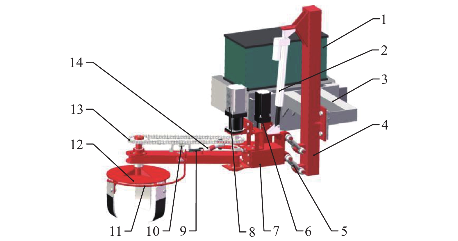
图 1 枸杞株间电驱动避障除草机结构示意图
1. 蓄电池组 2. 电动推杆 3. 主机架 4. 竖机架 5. 起降连杆 6. 伺服电机模块 7. 横机架 8. 直流电机模块 9. 气弹簧 10. 角度传感器 11. 触杆 12. 除草刀盘 13. 链传动 14.避障连杆
Figure 1. Structure diagram of the intra-row electric driven obstacle avoidance weeder for wolfberry
1. Battery pack 2. Electric push rod 3. Main frame 4. Vertical frame 5. Takeoff and landing linkage 6. Servo motor module 7. Horizontal frame 8. DC motor module 9. Gas spring 10. Angle sensor 11. Contact rod 12. Weeding cutter 13. Chain transmission 14. Obstacle avoidance connecting rod
![]()
图 2 整机工作原理示意图
1. 拖拉机前配重架 2. 主机架 3. 避障连杆 4. 枸杞行 5. 除草刀盘工作区域 6.枸杞植株
Figure 2. Schematic diagram of the working principle of the entire machine
1. Tractor front counterweight frame 2. Main frame 3. Obstacle avoidance connecting rod 4. wdfberry row 5. Weeding cutter working area 6. Lycium barbarum plant注:转动箭头表示避障连杆先顺时针转动,再逆时针转动复位。Note: The rotating arrow indicates that the obstacle avoidance connecting rod first rotates clockwise and then counterclockwise to reset.
![]()
图 3 整机起降机构示意图与受力分析图
注:A为电动推杆与竖机架的铰点;B为起降连杆与竖机架的铰点;C为起降连杆与横机架的铰点;D为电动推杆与横机架的铰点;E为重心在横机架上的投影点;F为电动推杆所受的拉力;G为传动装置、除草装置、自动避障机构的重力;H为过铰点D与AB平行线上的一点;J为EC延长线与AB的交点;l为电动推杆上铰点A到起降连杆上铰点B的长度,mm;l1为重力G相对于铰点C的重心距,mm;l2为重力G相对于铰点D的距离,mm;l3为起降连杆上铰点B到C的长度 ,mm;α为起降连杆BC与AB的夹角,(°);θ1为电动推杆AD与AB的夹角,(°);θ2为电动推杆AD与DH夹角,(°)。
Figure 3. Schematic diagram and force analysis diagram of the take-off and landing mechanism
Note: A is the hinge point between the electric push rod and the vertical frame; B is the hinge point between the takeoff and landing linkage and the vertical frame; C is the hinge point between the takeoff and landing linkage and the horizontal frame; D is the hinge point between the electric push rod and the horizontal frame; E is the projection point of the center of gravity on the horizontal frame; F is the tensile force exerted on the electric push rod; G is the gravity of the transmission device, weed control device, and automatic obstacle avoidance mechanism; H is a point on the parallel line between hinge point D and AB; J is the intersection point of EC extension line and AB; l is the length from hinge point A on the electric push rod to hinge point B on the takeoff and landing linkage, mm; l1 is the distance between the center of gravity G and hinge point C, mm; l2 is the distance between gravity G and hinge point D, mm; l3 is the length of hinge point B to C on the take-off and landing linkage , mm; α is the angle between takeoff and landing linkage BC and AB, (°); θ1 is the angle between the electric push rod AD and AB, (°); θ2 is the angle between electric push rod AD and DH , (°).
![]()
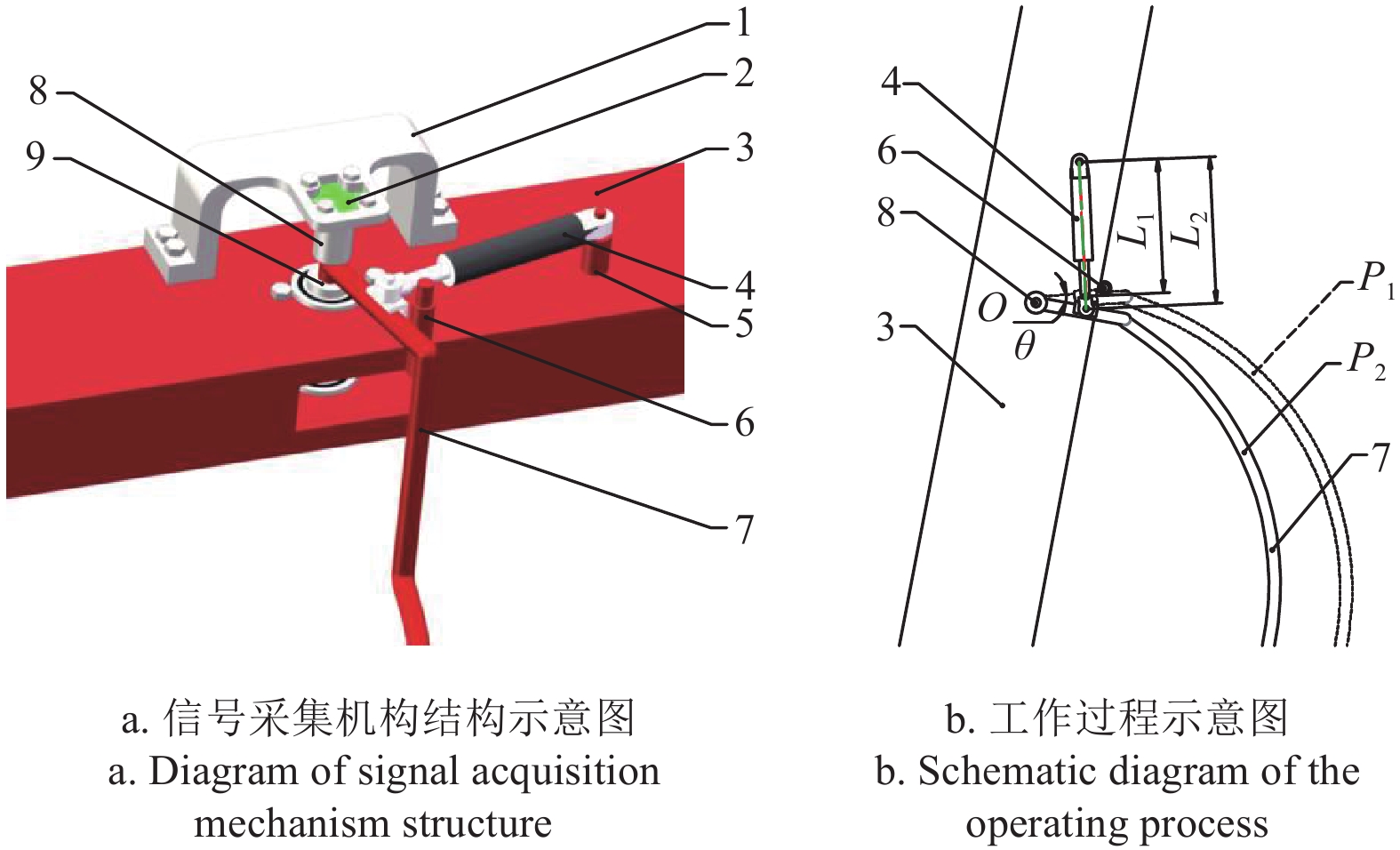
图 4 信号采集机构结构与工作过程示意图
1. 传感器支架 2. 角度传感器 3. 长臂 4. 气弹簧 5. 气弹簧安装架 6. 限位杆 7. 触杆 8. 圆磁铁支座 9. 触杆转轴 1. Sensor bracket 2. Angle sensor 3. Long arm 4. Gas spring 5. Gas spring mount 6. Limit rod 7. Contact rod 8. Round magnet support 9. Contact rod rotation shaft注:O为触杆的安装位置与旋转中心;P1为触杆的初始位置;P2是触杆接触到枸杞植株绕O点偏转后的位置;L1为气弹簧初始长度,mm;L2为气弹簧拉伸后的最大长度,mm;θ为触杆绕O点旋转的最大角度,(°)。
Figure 4. Schematic diagram of signal acquisition mechanism and operating process
Note:O is the installation position and rotation center of the contact rod; P1 is the initial position of the lever; P2 is the position where the contact rod contacts the lycium barbarum plant and deflects around point O; L1 is the initial length of the gas spring, mm; L2 is the maximum length of the gas spring after stretching, mm; θ is the maximum angle at which the contact rod rotates around point O, (°).
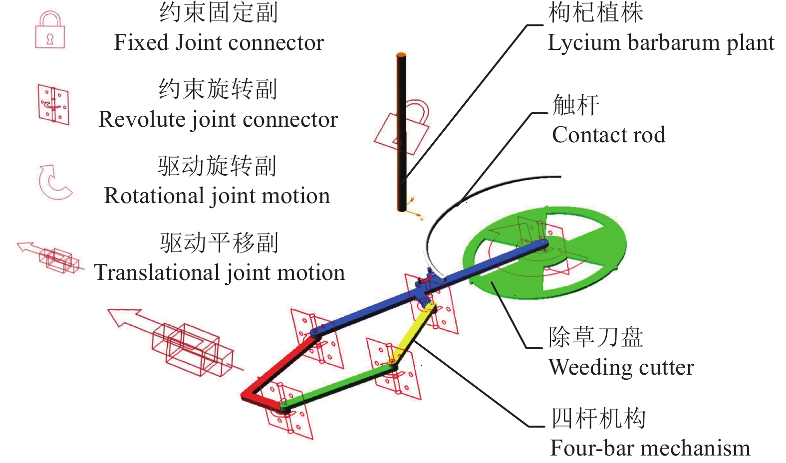
![]()
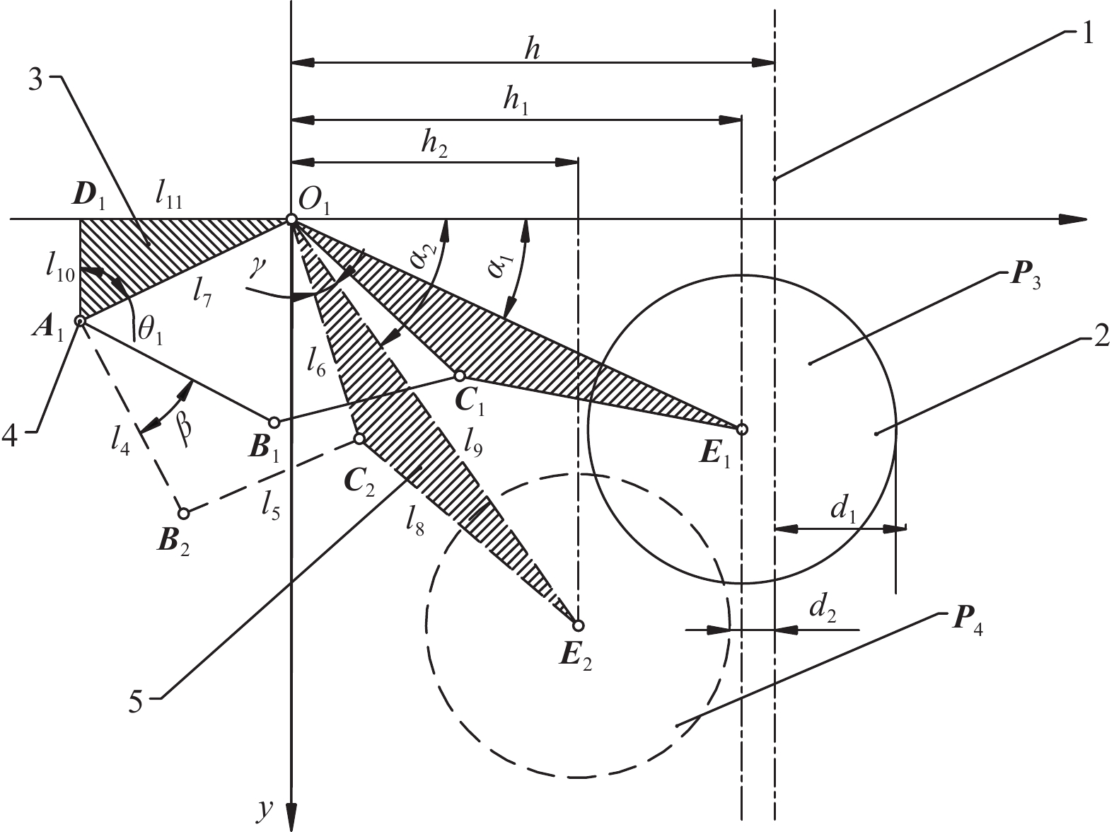
图 5 避障机构二维运动模型
1. 枸杞行 2. 除草刀盘 3. 横机架 4. 伺服电机模块 5. 长臂
Figure 5. Two-dimensional motion model of obstacle avoidance mechanism
1. Lycium barbarum row 2. Weeding cutter 3. Horizontal frame 4. Servo motor module 5. Long arm 注:P3为除草刀盘在株间工作时的位置;P4为除草刀盘在行内工作时的位置;l4为四杆机构中主动杆A1B2的长度,mm;l5为四杆机构中连接杆B2C2的长度,mm;l6为长臂旋转中心O1到铰点C2的长度,mm;l7为横机架上铰点A1到铰点O1的长度,即固定杆的长度,mm;l8为长臂上铰点C2到刀盘旋转中心E2的长度,mm;l9为长臂上铰点O1到刀盘旋转中心E2的长度,mm;l10为横机架上△A1D1O1中短直角边A1D1的长度,mm;l11为横机架上△A1D1O1中长直角边O1D1的长度,mm;h为横机架末端O1到枸杞行中心线的垂直长度,mm;h1为P3位置时长臂沿x方向上的长度,mm;h2为P4位置时长臂沿x方向上的长度,mm;d1为P3位置时除草刀盘伸入株间的长度,mm;d2为P4位置时除草刀盘边缘距离枸杞行的长度,mm;α1为E1O1与x轴正方向的夹角,(°);α2为E2O1与x轴正方向的夹角,(°);β为B1A1与B2A1的夹角,即从P3位置到P4位置主动杆转过的角度,(°);γ为长臂上E2O1与C2O1的夹角,(°);θ1为横机架上D1A1与O1A1的夹角,(°)。Note: P3 is the position of the weeding cutter when working in intra-row; P4 is the position of the weeding cutter when working in inter-row; l4 is the length of the active rod A1B2 in the four bar mechanism, mm; l5 is the length of the connecting rod B2C2 in the four bar mechanism, mm; l6 is the length from the rotation center O1 of the long arm to the hinge point C2, mm; l7 is the length from hinge point A1 to hinge point O1 on the horizontal frame, mm; l8 is the length from the hinge point C2 on the long arm to the rotation center E2 of the weeding cutter , mm; l9 is the length from the rotation center E2 of the weeding cutter to hinge point O1 on the long arm, mm; l10 is the length of the short right angle edge AD in △A1D1O1 on the horizontal frame, mm; l11 is the length of the long right angle edge O1D1 in △A1D1O1 on the horizontal frame, mm; h is the vertical length from the end O1 of the crossbar to the center line of the lycium barbarum row, mm; h1 the length of the long arm in the x-direction at position P3, mm; h2 the length of the long arm in the x-direction at position P4, mm; d1 is the length of the weeding cutter inserted between plants at position P3, mm; d2 is the distance between the edge of the weeding cutter and the lycium barbarum row at position P4, mm; α1 is the angle between E1O1 and the positive x-axis direction, (°);α2 is the angle between E2O1 and the positive x-axis direction, (°);β is the angle between B1A1 and B2A1, which is the angle at which the active rod rotates from position P3 to position P4, (°); γ is the angle between E2O1 and C2O1 on the long arm, (°); θ1 is the angle between D1A1 and O1A1 on the horizontal frame, (°).
![]()
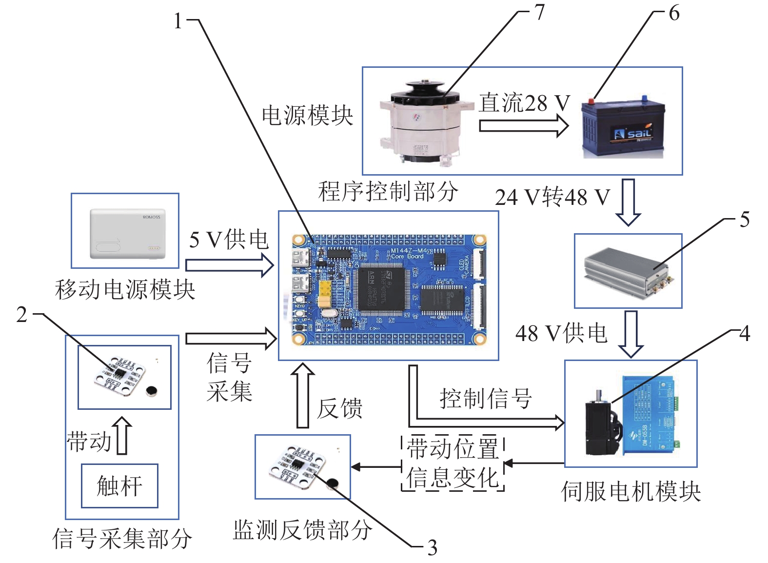
图 6 控制系统硬件组成
1. STM32F407最小系统板 2. 信号采集角度传感器 3. 监测反馈角度传感器 4. 伺服电机与驱动器 5. 24 V转48 V升压模块 6. 蓄电池组 7. 直流发电机
Figure 6. Hardware composition of control system
1. STM32F407 minimum system board 2. Signal acquisition angle sensor 3. Monitoring feedback angle sensor 4. Servo motor and driver 5. 24 V to 48 V boost module 6. Battery pack 7. DC generator
![]()
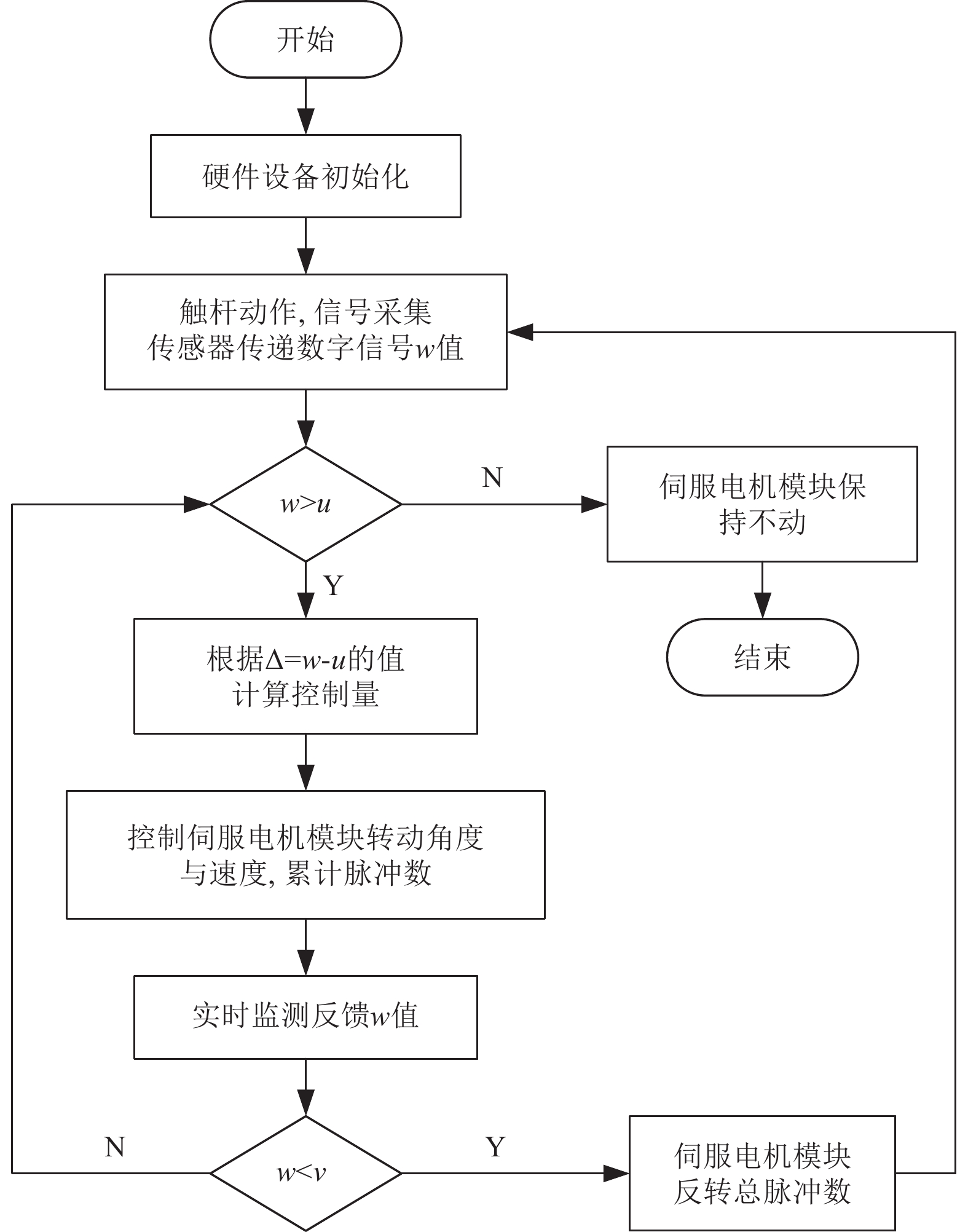
图 7 控制系统软件流程
注:u为角度上阈值;v为角度下阈值。
Figure 7. Software flow of control system
Note:u is the upper threshold of angle; v is the lower threshold of angle.
![]()
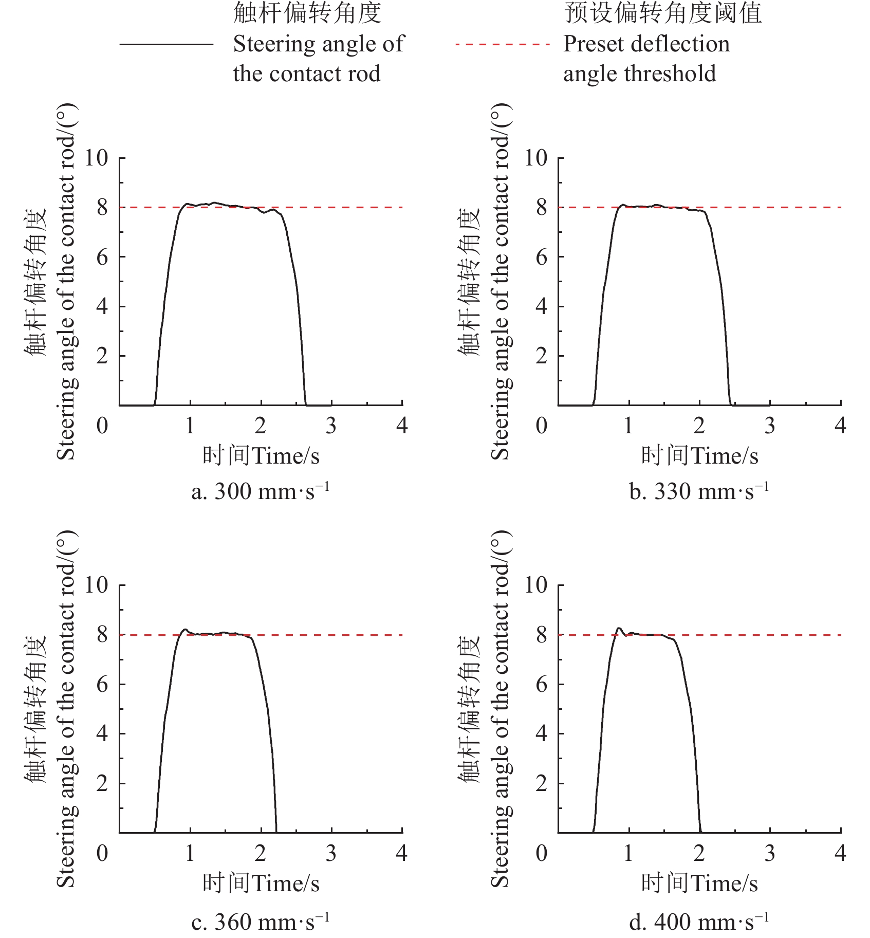
图 8 不同前进速度下避障动作响应曲线
Figure 8. Response curve of obstacle avoidance action at different operating speeds
![]()
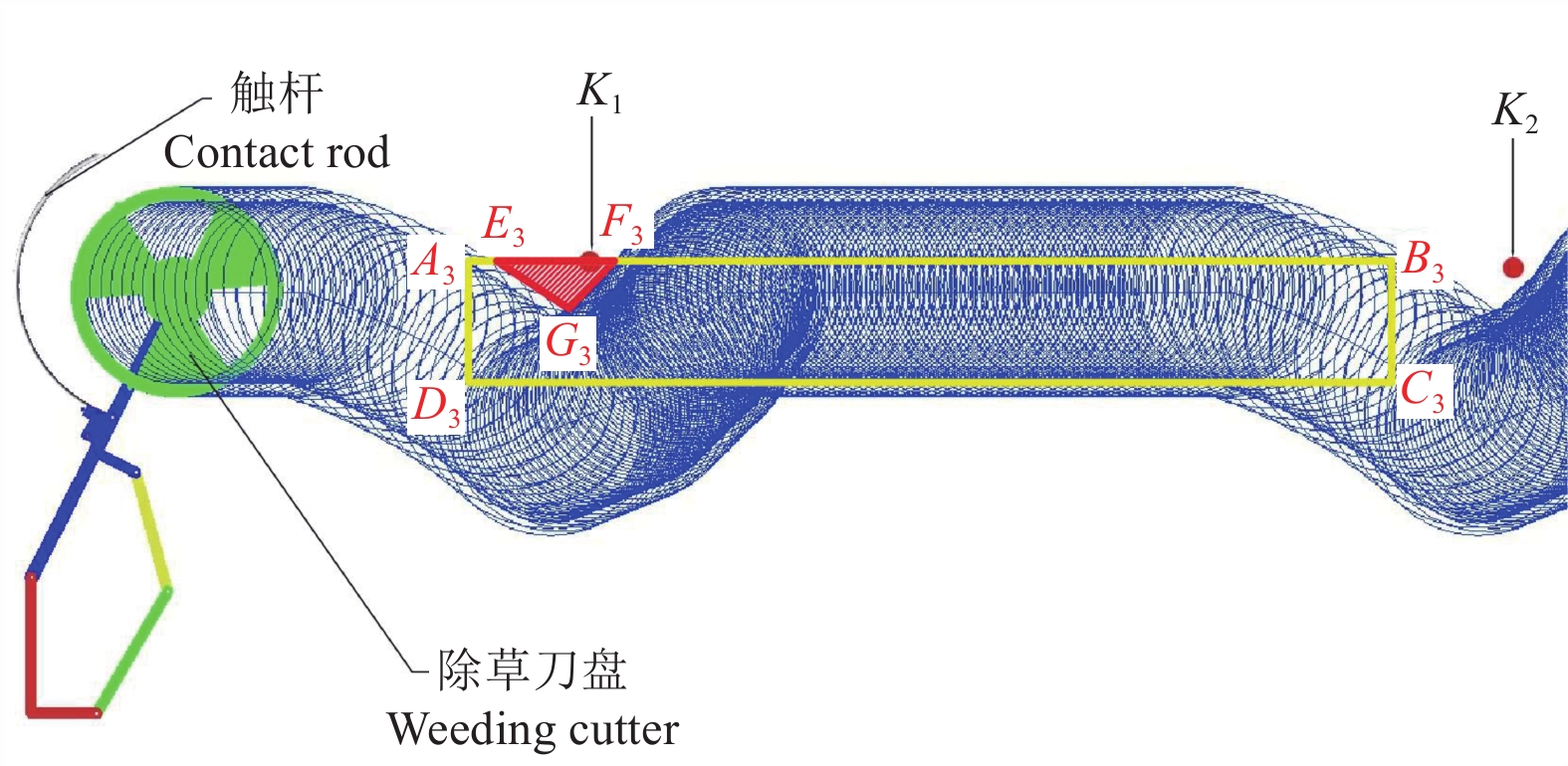
图 10 除草刀盘运动轨迹仿真效果图
注:K1, K2为障碍物;矩形A3B3C3D3为应除杂草区域;ΔE3F3G3为未除净杂草区域。
Figure 10. Simulation effect diagram of the movement trajectory of the weeding cutter
Note: K1, K2 is the obstacle; rectangular A3B3C3D3 is the theoretical weeding area; ΔE3F3G3 is the unworked area.
![]()
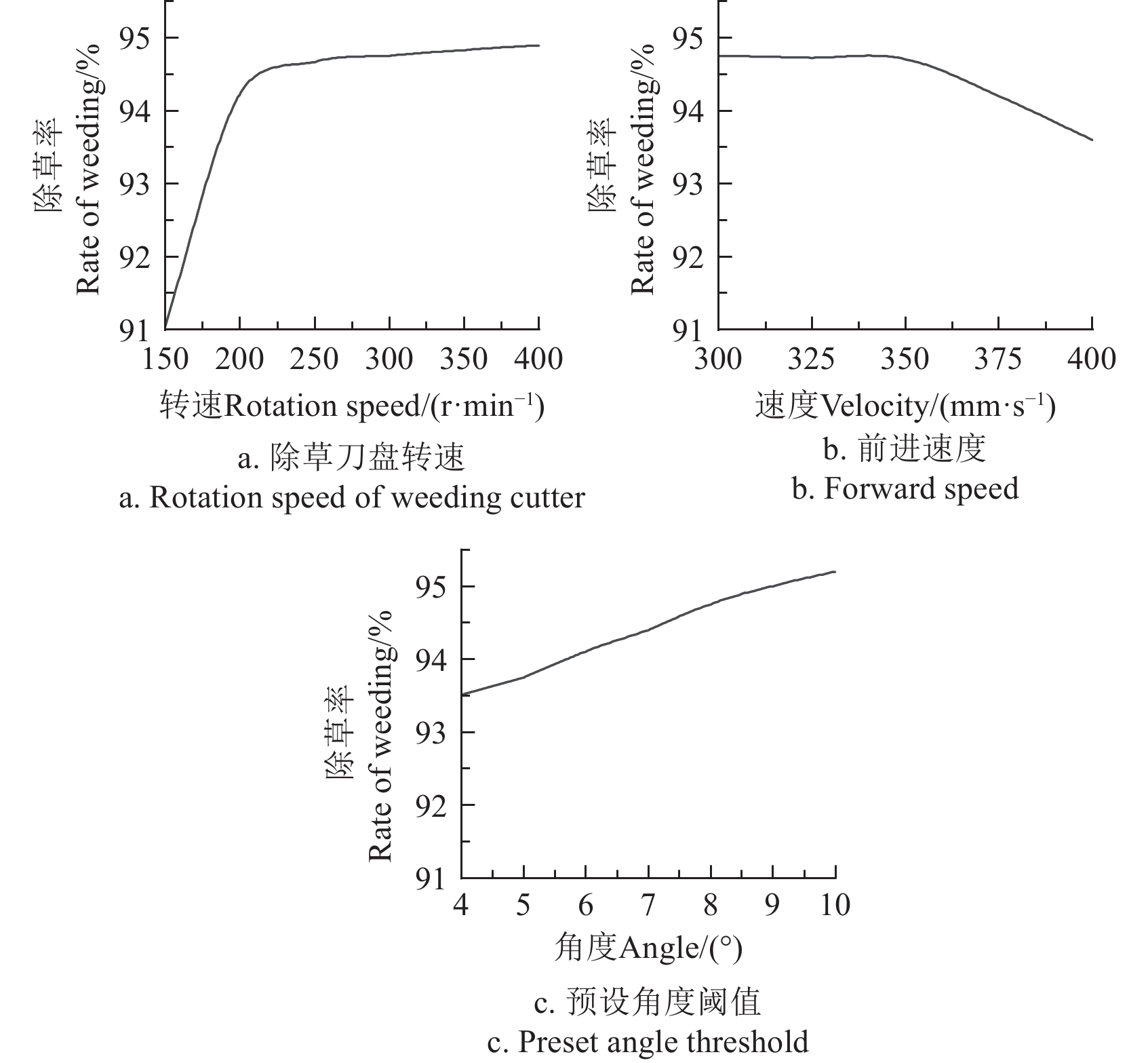
图 11 各因素对除草率影响的仿真曲线
Figure 11. Simulation curve of the impact of various factors on weed control rate
![]()
图 13 交互因子对除草率的影响
Figure 13. Influence of interaction factors on coverage rate of weeding
表 1 因素水平编码
Table 1 Levels encoding of factors
水平
Levels前进速度
Forward speed/
(mm·s−1)除草刀盘转速
Rotation speed of
weeding cutter/ (r·min−1)预设角度阈值
Preset angle
threshold/(°)−1 300 200 6 0 350 250 8 1 400 300 10  下载: 导出CSV
表 2 试验设计与结果
Table 2 Experimental design and results
序号
Serial No.X1 X2 X3 除草率
Rate of weeding/%1 −1 −1 0 89.76 2 1 −1 0 89.36 3 −1 1 0 90.68 4 1 1 0 90.45 5 −1 0 −1 90.22 6 1 0 −1 88.12 7 −1 0 1 90.92 8 1 0 1 90.78 9 0 −1 −1 88.12 10 0 1 −1 90.06 11 0 −1 1 90.72 12 0 1 1 91.01 13 0 0 0 90.66 14 0 0 0 90.45 15 0 0 0 90.42 16 0 0 0 90.02 17 0 0 0 90.87 注:X1、X2、X3分别为前进速度、除草刀盘转速、预设角度阈值的水平值。 Note: X1、X2、X3 are the levels of operating speed, rotation speed of weeding cutter, preset angle threshold.
下载: 导出CSV
表 3 回归方程方差分析
Table 3 Regression equation analysis of variance
方差来源
Variation source平方和
Sum of
squares自由度
Degree of
freedomF P 模型Model 10.69 6 12.11 0.0004 X1 1.03 1 7.00 0.0245 X2 2.32 1 15.78 0.0026 X3 5.75 1 39.05 < 0.0001 X1X2 0.0072 1 0.049 0.8291 X1X3 0.96 1 6.53 0.0286 X2X3 0.62 1 4.24 0.0665 残差Residual 1.47 10 失拟项Lack of fit 1.07 6 1.78 0.2996 纯误差Pure error 0.40 4 总值Total value 12.16 16 注:P<0.01表示极显著;P<0.05表示显著。 Note: P<0.01 indicates extremely significant;P<0.05 indicates significant.
下载: 导出CSV
-
[1] 于威,韩晓梅. 现代化果园机械除草装备与技术应用现状及发展趋向[J]. 现代农村科技,2017(6):97. doi: 10.3969/j.issn.1674-5329.2017.06.086 [2] 尚书旗,王东伟,鹿光耀. 我国葡萄机械化生产现状与发展趋势[J]. 农机科技推广,2014(5):7-9. [3] 王奇,周文琪,唐汉,等. 弧齿往复式稻田株间自动避苗除草装置设计与试验[J]. 农业机械学报,2021,52(6):53-61,72. doi: 10.6041/j.issn.1000-1298.2021.06.006 WANG Qi, ZHOU Wenqi, TANG Han, et al. Design and experiment of arc-tooth reciprocating motion type seedling avoided weeding control device for intertillage paddy[J]. Transactions of the Chinese Society for Agricultural Machinery, 2021, 52(6): 53-61,72. (in Chinese with English abstract) doi: 10.6041/j.issn.1000-1298.2021.06.006
[4] 张斌. 果园株间除草自动让树装置的设计与研究[D]. 石河子:石河子大学,2017. ZHANG Bin. Design and Research for Equipment of Allowing Trees for Weeding Among Plants [D]. Shihezi: Shihezi University, 2017. (in Chinese with English abstract [5] 杨硕,李法德,闫银发,等. 果园株间机械除草技术研究进展与分析[J]. 农机化研究,2020,42(10):1-8,16. doi: 10.3969/j.issn.1003-188X.2020.10.001 YANG Shuo, LI Fade, YAN Yinfa, et al. Multi-roller dynamic balance test bench design and modal analysis[J]. Journal of Agricultural Mechanization Research, 2020, 42(10): 1-8,16. (in Chinese with English abstract) doi: 10.3969/j.issn.1003-188X.2020.10.001
[6] 陈子文,张春龙,李南,等. 智能高效株间锄草机器人研究进展与分析[J]. 农业工程学报,2015,31(5):1-8. doi: 10.3969/j.issn.1002-6819.2015.05.001 CHEN Ziwen, ZHANG Chunlong, LI Nan, et al. Study review and analysis of high performance intra-row weeding robot[J]. Transactions of the Chinese Society of Agricultural Engineering (Transactions of the CSAE), 2015, 31(5): 1-8. (in Chinese with English abstract) doi: 10.3969/j.issn.1002-6819.2015.05.001
[7] 刘文,徐丽明,邢洁洁,等. 作物株间机械除草技术的研究现状[J]. 农机化研究,2017,39(1):243-250. doi: 10.3969/j.issn.1003-188X.2017.01.048 LIU Wen, XU Liming, XING Jiejie, et al. Research status of mechanical intra-row weed control in row crops[J]. Journal of Agricultural Mechanization Research, 2017, 39(1): 243-250. (in Chinese with English abstract) doi: 10.3969/j.issn.1003-188X.2017.01.048
[8] SAIMBHI V S, WADHWA D S, GREWAL P S. Development of a rotary tiller blade using three-dimensional computer graphics[J]. Biosystems Engineering, 2004, 89(1): 47-58. doi: 10.1016/j.biosystemseng.2004.05.011
[9] KATAOKA T, SHIBUSAWA S. Soil-blade dynamics in reverse-rotational rotary tillage[J]. Journal of Terramechanics, 2002, 39(2): 95-113. doi: 10.1016/S0022-4898(02)00004-6
[10] SALOKHE V M, RAMALINGAM N. Effect of rotation direction of a rotary tiller on draft and power requirements in a Bangkok clay soil[J]. Journal of Terramechanics, 2002, 39(4): 195-205. doi: 10.1016/S0022-4898(03)00013-2
[11] MAO P J, XING Q Q, HU C Y. The establishment and analysis on mathematical model of rotary cultivator power consumption[J]. Applied Mechanics and Materials, 2012, 159: 366-370. doi: 10.4028/www.scientific.net/AMM.159.366
[12] ABO-ELNOR M, HAMILTON R, BOYLE J T. 3D Dynamic analysis of soil–tool interaction using the finite element method[J]. Journal of Eerramechanics, 2003, 40(1): 51-62. doi: 10.1016/j.jterra.2003.09.002
[13] CORDILL C, GRIFT T E. Design and testing of an intra-row mechanical weeding machine for corn[J]. Biosystems Engineering, 2011, 110(3): 247-252. doi: 10.1016/j.biosystemseng.2011.07.007
[14] MIDTIBY H S, GISELSSON T M, JøRGRNSEN R N. Estimating the plant stem emerging points (PSEPs) of sugar beets at early growth stages[J]. Biosystems Engineering, 2012, 111(1): 83-90. doi: 10.1016/j.biosystemseng.2011.10.011
[15] 王兴林,邸伟,郭金太,等. 我国机械化耕整地技术发展初探[J]. 农业科技与装备,2011(6):101-102. doi: 10.3969/j.issn.1674-1161.2011.06.038 WANG Xinglin, DI Wei, GUO Jintai, et al. Discussion on the development of mechanized tillage and soil preparation technology in China[J]. Agricultural Science & Technology and Equipmen, 2011(6): 101-102. (in Chinese with English abstract) doi: 10.3969/j.issn.1674-1161.2011.06.038
[16] 中国农业机械化科学研究院. 农业机械设计手册[Z]. 北京:中国农业科学技术出版社,2007. [17] 张文帝,黄盛杰,金亦富. 果园除草机技术研究现状及发展对策[J]. 农业装备技术,2023,49(1):4-6. doi: 10.3969/j.issn.1671-6337.2023.01.002 [18] 王磊,张斌,张宏文,等. 果园株间除草自动让树装置的设计[J]. 农机化研究,2018,40(10):69-74. doi: 10.3969/j.issn.1003-188X.2018.10.013 WANG Lei, ZHANG Bin, ZHANG Hongwen, et al. The design equipment of allowing trees for weeding among plants[J]. Journal of Agricultural Mechanization Research, 2018, 40(10): 69-74. (in Chinese with English abstract) doi: 10.3969/j.issn.1003-188X.2018.10.013
[19] 徐丽明,于畅畅,刘文,等. 篱架式栽培葡萄株间除草机自动避障机构优化设计[J]. 农业工程学报,2018,34(7):23-30. XU Liming, YU Changchang, LIU Wen, et al. Design and experiment of bilateral operation intra-row auto obstacle avoidance weeder for trellis cultivated grape[J]. Transactions of the Chinese Society of Agricultural Engineering (Transactions of the CSAE), 2019, 35(5): 1-9. (in Chinese with English abstract)
[20] 徐丽明,赵诗建,马帅,等. 葡萄株间除草机精准避障控制系统优化设计与试验[J]. 农业工程学报,2021,37(15):31-39. doi: 10.11975/j.issn.1002-6819.2021.15.004 XU Liming, ZHAO Shijian, MA Shuai, et al. Optimized design and experiment of the precise obstacle avoidance control system for a grape interplant weeding machine[J]. Transactions of the Chinese Society of Agricultural Engineering (Transactions of the CSAE), 2021, 37(15): 31-39. (in Chinese with English abstract) doi: 10.11975/j.issn.1002-6819.2021.15.004
[21] 王永烁,康建明,彭强吉,等. 果树株间避障除草机设计与试验[J]. 吉林大学学报(工学版),2023,53(8):2410-2420. WANG Yongshuo, KANG Jianming, PENG Qiangji, et al. Design and experiment of obstacle avoidance weeding machine for fruit trees[J]. Journal of Jilin University(Engineering and Technology Edition), 2023, 53(8): 2410-2420. (in Chinese with English abstract)
[22] 李建新. 果园株间自动避障除草装置的设计与研究[D]. 石河子:石河子大学,2020. LI Jianxin. Design and Research of an Automatic Obstacle Avoidance Device for Weeding Between Plants in Orchards[D]. Shihezi: Shihezi University, 2020. (in Chinese with English abstract [23] 李建新,李文春,陈廷官,等. 果园除草机避让系统设计及仿真[J]. 江苏农业科学,2019,47(9):248-251,262. [24] 宋裕民,高琦,许宁,等. 新能源智能农机装备发展现状和趋势[J]. 农业装备与车辆工程,2024,62(1):1-6. doi: 10.3969/j.issn.1673-3142.2024.01.001 SONG Yumin, GAO Qi, XU Ning, et al. Development status and trend of new energy intelligent agricultural machine[J]. Agricultural Equipment & Vehicle Engineering, 2024, 62(1): 1-6. (in Chinese with English abstract) doi: 10.3969/j.issn.1673-3142.2024.01.001
[25] IGAWA H, TANAKA T, KANEKO S, et al. Base position detection of grape stem considering its displacement for weeding robot in vineyards[C]//IECON 2012-38th Annual Conference on IEEE Industrial Electronics Society. IEEE, 2012: 2567-2572.
[26] REISER D, SEHSAH E S, BUMANN O, et al. Development of an autonomous electric robot implement for intra-row weeding in vineyards[J]. Agriculture, 2019, 9(1): 18. doi: 10.3390/agriculture9010018
[27] 马锃宏,李南,王汉斌,等. 温室株间电驱锄草机控制系统设计与试验[J]. 农业机械学报,2015,46(1):89-93. doi: 10.6041/j.issn.1000-1298.2015.01.013 MA Zenghong, LI Nan, WANG Hanbin, et al. Control system for electric drive intra-row weeding[J]. Transactions of the Chinese Society for Agricultural Machinery, 2015, 46(1): 89-93. (in Chinese with English abstract) doi: 10.6041/j.issn.1000-1298.2015.01.013
[28] 卢营蓬,易文裕,程方平,等. 轻简型桑园电动除草机设计与试验[J]. 中国农机化学报,2020,41(9):76-81. LU Yingpeng, YI Wenyu, CHENG Fangping, et al. Design and experiment of light-weight electric weeder for mulberry garden[J]. Journal of Chinese Agricultural Mechanization, 2020, 41(9): 76-81. (in Chinese with English abstract)
[29] 李寅男. 果园轮式除草机的设计与仿真研究[D]. 济南:山东交通学院,2023. LI Yinnan. Research on Design and Simulation of Orchard Wheel Weeding Machine [D]. Jinan: Shandong Jiaotong University, 2023. (in Chinese with English abstract [30] 高连兴,梁港平,蔡依琳,等. 铲齿-双滚筒组合式花生捡拾装置研制[J]. 农业工程学报,2024,40(12):13-22. doi: 10.11975/j.issn.1002-6819.202311186 GAO Lianxing, LIANG Gangping, CAI Yilin, et al. Pickup device with shovel teeth and double cylindersfor the bunch of peanuts[J]. Transactions of the Chinese Society of Agricultural Engineering (Transactions of the CSAE), 2024, 40(12): 13-22. (in Chinese with English abstract) doi: 10.11975/j.issn.1002-6819.202311186


计量
- 文章访问数: 158
- HTML全文浏览量: 21
- PDF下载量: 94