Combined positioning method for a mobile platform in facility horticulture based on UWB-IMU
-
摘要:
为解决设施场景下遮挡严重所致的电驱移动平台定位精度低、稳定性差的问题,该研究设计了基于超宽带(ultra wide band,UWB)和惯性测量单元(inertial measurement unit,IMU)的组合定位方法,并提出基于卡尔曼滤波的自适应抗差组合定位算法(adaptive robust combination positioning algorithm,ARCPA)。首先,针对单传感器定位误差大的问题,搭建基于UWB与IMU两种传感器的组合定位系统;其次,为精准检测UWB数据的非视距误差,设计差分距离非视距误差检测滑动窗口;最后,为抑制卡尔曼滤波中的量测噪声,采用余弦重启函数实时调整渐消因子,并引入位置精度因子权值修正抗差因子。为验证所提定位方法的有效性,搭建设施园艺电驱移动平台和实时定位系统,并进行仿真与实车定位试验。试验结果表明,采用所提UWB-IMU组合定位方法的均方根误差为
6.63 cm,比单传感器的定位精度提高了81.92%,相比于经典卡尔曼滤波、无迹卡尔曼滤波、扩展卡尔曼滤波、粒子滤波与自适应抗差卡尔曼滤波算法,所提ARCPA算法定位精度分别提高50.15%、74.63%、60.01%、60.88%、28.34%。研究结果可为设施园艺环境下的定位导航提供理论依据和实施方案。Abstract:Protected horticulture is required for the high positioning accuracy and stability of mobile platforms. However, the electric drive mobile platforms can be often confined to object obstruction under the natural scenes. In this study, a high-precision positioning system was designed using an ultra-wide band (UWB) and inertial measurement unit (IMU). Additionally, an adaptive robust combination positioning algorithm (ARCPA) with Kalman filtering was developed to effectively improve positioning accuracy and stability. Firstly, a multi-sensor integrated positioning was constructed to combine UWB and IMU. Secondly, a differential distance-based sliding window was introduced to precisely detect nonline of sight (NLOS) errors in the positioning data of UWB. Thirdly, a cosine restart function was used to dynamically adjust the fading factor in real time, in order to reduce the interference of noise fluctuations in Kalman filtering. The accuracy and robustness of the filter were enhanced after optimization. Finally, a position dilution of precision (PDOP) weighted robust factor was incorporated to improve the resilience of the positioning system against noise and model disturbances under-protected horticulture scenes. An electric drive mobile platform and real-time positioning were constructed to verify the effectiveness of the integrated system. Then the simulation and real experiments of vehicle positioning were conducted in the typical protected horticulture. The experimental results demonstrate that the root-mean-square errors before and after UWB ranging correction under line-of-sight condition were 119.0 and 49.0 cm, respectively, and the ranging accuracy was improved by 58.8% after correction. The positioning error of the integrated positioning was only 6.63 cm, which was 81.92% higher than that of the single sensor (36.68 cm). The maximum error of positioning accuracy was also reduced by 88.89%. Therefore, this integrated positioning significantly reduced the impact of NLOS and geometric error on the positioning accuracy of the electric drive mobile platform for protected horticulture. Moreover, the root-mean-square error and the maximum positioning error of ARCPA were 17.70 and 44.44 cm, respectively. Furthermore, the accuracy of the improved system increased by 50.15%, 74.63%, 60.01%, 60.88%, and 28.34%, respectively, compared with the Kalman filtering, unscented Kalman filtering, extended Kalman filtering, particle filtering, and adaptive robust Kalman filtering. Correspondingly, the maximum positioning error was then reduced by 66.83%, 73.67%, 69.07%, 71.2%, and 50.50%, respectively. The integrated positioning significantly improved the robustness of the electric drive mobile platform for protected horticulture. The finding can also provide a specific theoretical basis and plan for the positioning and navigation in a protected horticulture environment.
-
0. 引 言
随着农业科技水平的提高,设施园艺逐步实现机械化、自动化、信息化生产,并向智能化转型[1-4]。开发适合设施园艺应用的智能作业机械成为当前研究的热点,其中精准定位对于引导移动作业机械自主行驶与作业至关重要。设施园艺具有非结构化和高度可变的复杂环境,且存在大量的人工设施[5],为获得高度自主移动性,往往需要安装复杂、全面的传感器以获得更精确稳定的定位。目前,完全自动化的解决方案尚未在设施园艺领域实施。
设施园艺环境中无法采用常用的全球导航卫星系统(global navigation satellite system,GNSS)信号[6],因此需要一种可替代的实时定位系统,以满足设施园艺精确定位的要求。目前,各种室内定位方案都取得了巨大的发展,并在实践中得到了广泛应用,包括声定位、同步定位与地图构建(simultaneous localization and mapping,SLAM)、超宽带(ultra wide band,UWB)等。HUANG等[7]采用载波频率检测的多普勒频移补偿算法提升补偿声信号的能力,实现了温室环境下的厘米级精度定位。声定位虽然可以实现低成本实时定位,但易受环境干扰且覆盖范围存在局限性。SLAM技术是近年来的热门研究方向,然而由于设施园艺环境的特殊性,限制了该方法在设施园艺定位领域的应用。设施园艺与大部分的室内环境不同,多跨大棚通常具有以下特点:(1)面积大且包含很少独特元素的空旷环境(农田、水泥路面、塑料薄膜、玻璃等);(2)整体结构高度重复且具有大量障碍物(大棚立柱、灌溉系统等);(3)作物生长导致环境动态变化[8-9]。因此,对于具有动态、大尺度、高重复的设施园艺环境,视觉SLAM和激光SLAM难以提取和匹配显著特征进行定位。超宽带具有低功耗、高精度、高分辨率和覆盖范围大等特点,成为设施园艺环境定位系统的研究热点。姚立健等[10]采用加权最小二乘法提高UWB定位精度,设计基于动态前视距离的纯跟踪模型,并通过试验证明了特定情况下基于UWB定位的可行性。解开婷等[11]提出一种全质心加权最小二乘的高速双边双向算法,通过组合固定解与模糊解,将定位目标求解转换为凸规划优化,解决了UWB因测距误差导致三角形公共区域缺失的问题。陈兆等[12]建立了UWB基站布设优化模型,使用遗传算法和萤火虫算法优化基站布设阵型,降低了定位误差的波动。LI等[13]提出一种基于预校正策略和粒子群优化算法的超宽带精确测距方法,进一步提高了UWB测距精度。然而,设施园艺中的复杂场景仍限制着UWB的使用,多径效应、基站布设等问题都会导致UWB定位精度出现较大的波动。此外,设施园艺中存在的铁架、大棚立柱、塑料薄膜、作物等,会在UWB数据中引入大量的非视距(non line of sight,NLOS)误差[14-15]。综上,单一传感器存在固有限制和缺陷,无法满足复杂场景的定位要求。因此,可尝试多传感器组合定位以增加定位的稳定性和可靠性。其中,IMU传感器具有短时精准位置估算的特点,可对UWB定位误差进行修正。此外,通过运用误差检测、修正策略、多传感器数据融合技术与各种滤波算法,可解决环境中的固定误差和传感器的累积误差,常用的滤波算法包括扩展卡尔曼滤波(extended kalman filtering,EKF)、Sage-Husa卡尔曼滤波(sage-husa kalman filtering,SHKF)、无迹卡尔曼滤波(unscented kalman filtering,UKF)和自适应卡尔曼滤波(adaptive kalman filtering,AKF)等[16-21]。这些组合定位方案及融合滤波算法在处理非线性系统、动态环境下的实时性和鲁棒性方面仍有较大改进空间[22]。
为此,本文提出一种基于自适应抗差组合定位算法(adaptive robust combination positioning algorithm,ARCPA)的UWB-IMU组合定位方法。首先,引入距离差分滑动窗口对UWB数据进行非视距误差鉴别。然后,为充分利用量测信息,提出余弦重启渐消因子,动态调整历史量测的权重。同时,为了减小几何误差的影响,设计基于位置精度因子权值的抗差因子。最后,通过仿真与实车定位试验验证所提组合定位方法的有效性。
1. UWB-IMU组合定位系统设计
1.1 设施园艺电驱移动平台
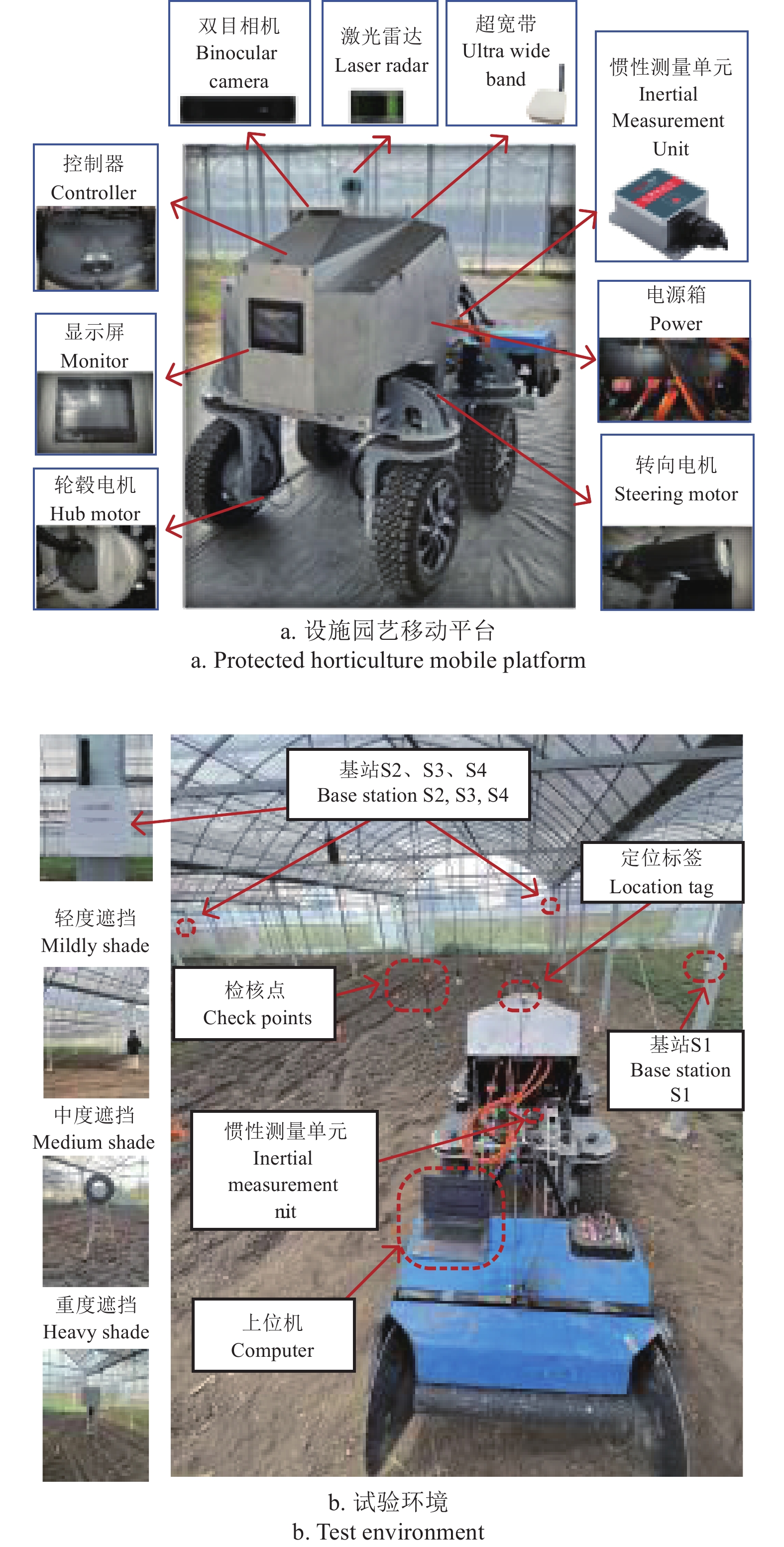
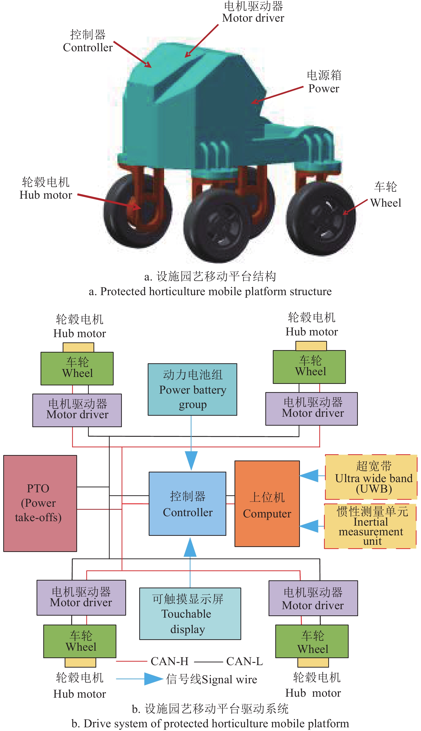
针对设施园艺特殊作业场景对电驱移动平台灵活作业与高操纵稳定性需求,设计了一种设施园艺电驱移动平台,整体结构设计如图1a所示。动力系统主要由轮毂电机、动力电池、整车控制器等组成,驱动系统结构如图1b所示。采用纯电动四轮独立转向-独立驱动机构,由锂电池(76.8 V、280 Ah)供电。
1.2 组合定位方法
在设施园艺场景下,作物种植密集且存在大量人工设施,UWB测距信号易受到周围环境的干扰,极大影响定位精度,而IMU可提供短时的精准定位信息,结合两者的信息可以显著改善系统的定位性能。
1.2.1 UWB定位原理
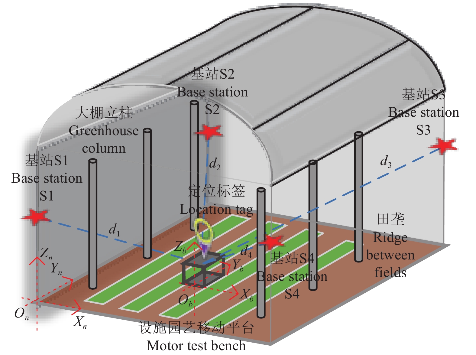
UWB定位系统如图2所示,在设施园艺场景中部署3个或3个以上的UWB基站,UWB标签固定于电驱移动平台机体。本文导航坐标系用n系表示,载体坐标系用b系表示,On固定于基站S1在设施园艺环境地面的投影,载体坐标系Ob与设施园艺移动平台固连。
![]() 图 2 设施园艺UWB定位系统注:Ob为载体坐标系,固连于移动平台,按“右前上”顺序定义,Xb沿载体横轴指向载体右侧,Yb沿载体横轴指向载体前方,Zb垂直Xb与Yb所在平面向上。On为导航坐标系,固定于基站S1的地面投影区域,Xn沿大棚横向指向大棚右侧,Yn沿大棚纵向指向大棚前方,Zn垂直Xn与Yn所在平面向上;d1,d2,d3,d4为定位标签到基站S1,S2,S3,S4距离,m。Figure 2. Protected horticulture UWB positioning systemNote: Ob is the carrier coordinate system, fixed to the mobile platform, defined in the order of “right front up”, with Xb pointing to the right side of the carrier along the transverse axis of the carrier, Yb pointing to the front of the carrier along the transverse axis of the carrier, and Zb perpendicularly upward in the plane where Xb and Yb are located. On is the navigation coordinate system fixed to the projection area of the base station S1 on the ground, Xn points to the right side of the shed along the transverse axis of the shed, Yn points to the front side of the shed along the longitudinal axis of the shed, and Zn is perpendicular to the plane upward where Xn and Yn are located; d1, d2, d3, and d4 denote the distances of the positioning tags to the base station S1, S2, S3, S4, m.
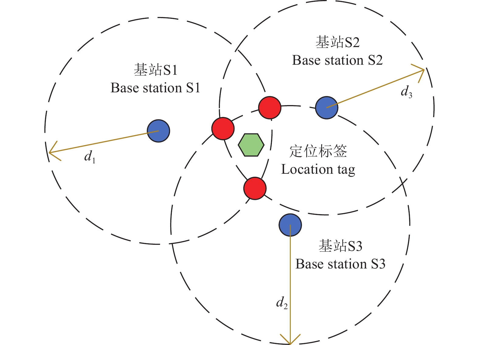
图 2 设施园艺UWB定位系统注:Ob为载体坐标系,固连于移动平台,按“右前上”顺序定义,Xb沿载体横轴指向载体右侧,Yb沿载体横轴指向载体前方,Zb垂直Xb与Yb所在平面向上。On为导航坐标系,固定于基站S1的地面投影区域,Xn沿大棚横向指向大棚右侧,Yn沿大棚纵向指向大棚前方,Zn垂直Xn与Yn所在平面向上;d1,d2,d3,d4为定位标签到基站S1,S2,S3,S4距离,m。Figure 2. Protected horticulture UWB positioning systemNote: Ob is the carrier coordinate system, fixed to the mobile platform, defined in the order of “right front up”, with Xb pointing to the right side of the carrier along the transverse axis of the carrier, Yb pointing to the front of the carrier along the transverse axis of the carrier, and Zb perpendicularly upward in the plane where Xb and Yb are located. On is the navigation coordinate system fixed to the projection area of the base station S1 on the ground, Xn points to the right side of the shed along the transverse axis of the shed, Yn points to the front side of the shed along the longitudinal axis of the shed, and Zn is perpendicular to the plane upward where Xn and Yn are located; d1, d2, d3, and d4 denote the distances of the positioning tags to the base station S1, S2, S3, S4, m.常用的UWB无线定位方法有到达时间法(time of arrival,TOA)、到达时间差法(time difference of arrival,TDOA)、基于信号到达角法(angle of arrival,AOA)和基于信号接收强度法(received signal strength indicator,SRS)[23]。本文使用基于测量信号到达时间法,测量基站与定位标签之间的距离,并采用三球交互定位方法估计UWB标签的位置(见图3)。
基站与定位标签之间的测量距离计算如下:
d=c⋅t+σ (1) 式中d为信号传播距离,m;t为信号传播时间,s;c为信号传播速度,m/s;σ为测量噪声与异常误差之和,m。
1.2.2 IMU定位原理
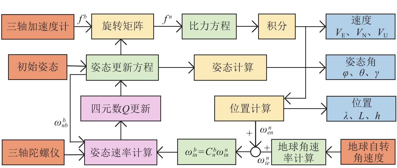
IMU主要由三轴加速度计和三轴陀螺仪组成[24],定位流程如图4所示,通过对输出的比力和角速度观测值进行积分运算,从而对载体位置、速度和姿态进行更新。
![]() 图 4 IMU定位解算原理注:λ和L分别表示经度和纬度,(°);h表示高度,m;φ、θ、γ表示俯仰角、航向角、横滚角,rad;VE、VN、VU表示东、北、天方向速度分量,m·s-1; \boldsymbol{\boldsymbol{f}}^{\mathit{b}} 和 \boldsymbol{\boldsymbol{f}}^{\mathit{n}} 表示b系和n系下的比力投影,m·s-2; \mathit{\omega}_{ie}^n 表示地球自转角速度矢量在导航坐标系中的投影,rad·s-1; {{{\omega}{_{en}^n}{{{ }}}}{ }} 表示导航坐标系下,地球自转和地球表面运动的角速度,rad·s-1; {\omega_{in}^b} 表示载体坐标系下,导航坐标系相对惯性坐标系的角速度,rad·s-1; \omega_{nb}^b 表示载体坐标系下,导航坐标系相对载体的角速度,rad·s-1; \omega_{in}^n 表示导航坐标系下,载体坐标系相对于惯性坐标系的角速度,rad·s-1。Figure 4. IMU (inertial measurement unit) positioning calculation principleNote: λ, L represent longitude, latitude, respectively, (°); h represent altitude, m; φ,θ,and γ denote the pitch angle, yaw angle, and roll angle, respectively, rad; VE, VN, and VU are the velocity components in east, north, and up directions, respectively, m·s-1; {\boldsymbol{f}}^b and \boldsymbol{f}^n refer to specific force projections in b-frame and the n-frame, respectively, m·s-2; \omega_{ie}^n represents projection of the Earth's rotation angular velocity vector in navigation coordinate system, rad·s-1; \omega_{en}^n denotes angular velocity in navigation coordinate system due to both Earth's rotation and movement on Earth's surface, rad·s-1; \omega_{in}^b indicates angular velocity of navigation coordinate system relative to inertial coordinate system in body coordinate system, rad·s-1; \omega_{nb}^b denotes angular velocity of navigation coordinate system relative to body in body coordinate system, rad·s-1; \omega_{in}^n represents angular velocity of body coordinate system relative to inertial coordinate system in the navigation coordinate system, rad·s-1.
图 4 IMU定位解算原理注:λ和L分别表示经度和纬度,(°);h表示高度,m;φ、θ、γ表示俯仰角、航向角、横滚角,rad;VE、VN、VU表示东、北、天方向速度分量,m·s-1; \boldsymbol{\boldsymbol{f}}^{\mathit{b}} 和 \boldsymbol{\boldsymbol{f}}^{\mathit{n}} 表示b系和n系下的比力投影,m·s-2; \mathit{\omega}_{ie}^n 表示地球自转角速度矢量在导航坐标系中的投影,rad·s-1; {{{\omega}{_{en}^n}{{{ }}}}{ }} 表示导航坐标系下,地球自转和地球表面运动的角速度,rad·s-1; {\omega_{in}^b} 表示载体坐标系下,导航坐标系相对惯性坐标系的角速度,rad·s-1; \omega_{nb}^b 表示载体坐标系下,导航坐标系相对载体的角速度,rad·s-1; \omega_{in}^n 表示导航坐标系下,载体坐标系相对于惯性坐标系的角速度,rad·s-1。Figure 4. IMU (inertial measurement unit) positioning calculation principleNote: λ, L represent longitude, latitude, respectively, (°); h represent altitude, m; φ,θ,and γ denote the pitch angle, yaw angle, and roll angle, respectively, rad; VE, VN, and VU are the velocity components in east, north, and up directions, respectively, m·s-1; {\boldsymbol{f}}^b and \boldsymbol{f}^n refer to specific force projections in b-frame and the n-frame, respectively, m·s-2; \omega_{ie}^n represents projection of the Earth's rotation angular velocity vector in navigation coordinate system, rad·s-1; \omega_{en}^n denotes angular velocity in navigation coordinate system due to both Earth's rotation and movement on Earth's surface, rad·s-1; \omega_{in}^b indicates angular velocity of navigation coordinate system relative to inertial coordinate system in body coordinate system, rad·s-1; \omega_{nb}^b denotes angular velocity of navigation coordinate system relative to body in body coordinate system, rad·s-1; \omega_{in}^n represents angular velocity of body coordinate system relative to inertial coordinate system in the navigation coordinate system, rad·s-1.首先通过四元数对姿态进行更新,姿态更新方程及姿态矩阵求解如下:
{{\boldsymbol{Q}}}_{b(k)}^{n}={{\boldsymbol{Q}}}_{b(k-1)}^{n}{{\boldsymbol{Q}}}_{b(k)}^{b(k-1)} (2) \begin{split} & \qquad\qquad {\boldsymbol{C}}_b^n= \\ & \left[\begin{array}{cccccccccccc}\ q_0^2+q_1^2-q_2^2-q_3^2\ \ \ 2(q_1q_2-q_0q_3)\ \ \ \ 2(q_1q_3+q_0q_2) \\ \ 2(q_1q_2+q_0q_3)\ \ \ \ q_0^2-q_1^2+q_2^2-q_3^2\ \ \ 2(q_2q_3-q_0q_1) \\ \ 2(q_1q_3-q_0q_2)\ \ \ \ 2(q_2q_3-q_0q_1)\ \ \ q_0^2-q_1^2-q_2^2+q_3^2\end{array}\right] \end{split} (3) 式中 \boldsymbol{Q}_{b\text{(}k)}^n=\left[q_0\ q_1\ q_2\ q_3\right]\mathrm{^T} 为k时刻导航坐标系下的姿态四元数, \boldsymbol{\boldsymbol{Q}}_{b\left(k\right)}^{b\left(k-1\right)} 为k-1与k时刻之前的四元数变化量,Q为四元数,C为方向余弦矩阵,上角标表示所处坐标系,下角标表示转换坐标系。
采用惯导比力方程和位置微分方程对速度、位置进行更新:
{\dot{{\boldsymbol{V}}}}^{n}={{\boldsymbol{C}}}_{b}^{n}{{\boldsymbol{f}}}^{b}-(2{\omega }_{ie}^{n}+{\omega }_{en}^{n})\times {{\boldsymbol{V}}}^{n}+{g}^{n} (4) \left\{\begin{aligned} & \dot{L}=\frac{{V}_{\text{N}}^{}}{{R}_{\text{m}}+h}\\ & \dot{\lambda }=\frac{{V}_{\text{E}}^{}}{({R}_{\text{n}}+h)\mathrm{cos}L}\\ & \dot{h}={V}_{\text{U}}^{}\end{aligned}\right. (5) 式中V为载体速度,m/s;gn为重力加速度在n系下的分量,m/s;Rm和Rn为子午圈半径和卯酉圈半径,m。
2. 基于UWB-IMU的组合定位算法
为满足设施园艺移动平台高精度定位要求,本文提出一种基于卡尔曼滤波的自适应抗差组合定位算法,设计一种差分距离非视距误差检测滑动窗口,同时引入余弦重启渐消因子和位置精度因子(position dilution of precision,PDOP)权值抗差因子,对移动平台运动状态进行实时精准估计。
2.1 自适应抗差原理
采用15维状态变量组建导航系统的状态方程,在导航坐标系中表示为
{{\boldsymbol{X}}_k} = {\left[ {\begin{array}{*{20}{c}} {{{\boldsymbol{\phi}} ^{\text{T}}}}&{\delta {{\boldsymbol{V}}^{\text{T}}}}&{\delta {{\boldsymbol{P}}^{\text{T}}}}&{\varepsilon _{\text{g}}^{\text{T}}}&{{\boldsymbol{\nabla}} _{\text{a}}^{\text{T}}} \end{array}} \right]^{\text{T}}} (6) 式中φT为失准角,δVT为车辆速度误差,δPT为位置误差,{\varepsilon _{\text{g}}^{\text{T}}} 为陀螺角零偏,{\boldsymbol{\nabla}}_{\mathrm{a}}^{\mathrm{T}} 为加速度计零偏。
结合惯性导航误差微分方程可得系统状态方程为
{{\boldsymbol{X}}_k} = {\boldsymbol{F}}{{\boldsymbol{X}}_{k - 1}} + {\boldsymbol{G}}{{\boldsymbol{W}}_k} (7) \boldsymbol{F}=\left[\begin{array}{*{20}{c}}\boldsymbol{O}_{\text{3}\times\text{3}} & \boldsymbol{O}_{\text{3}\times\text{3}} & \boldsymbol{O}_{\text{3}\times\text{3}} & -\boldsymbol{C}_n^b & \boldsymbol{O}_{\text{3}\times\text{3}} \\ (\boldsymbol{f}_{\text{sf}}^n)^* & \boldsymbol{O}_{\text{3}\times\text{3}} & \boldsymbol{O}_{\text{3}\times\text{3}} & \boldsymbol{O}_{\text{3}\times\text{3}} & \boldsymbol{C}_n^b \\ \boldsymbol{O}_{\text{3}\times\text{3}} & \boldsymbol{I}_{3\times3} & \boldsymbol{O}_{\text{3}\times\text{3}} & \boldsymbol{O}_{\text{3}\times\text{3}} & \boldsymbol{O}_{\text{3}\times\text{3}} \\ \boldsymbol{O}_{\text{3}\times\text{3}} & \boldsymbol{O}_{\text{3}\times\text{3}} & \text{O}_{\text{3}\times\text{3}} & -\boldsymbol{B}_{\text{G}} & \boldsymbol{O}_{\text{3}\times\text{3}} \\ \boldsymbol{O}_{\text{3}\times\text{3}} & \boldsymbol{O}_{\text{3}\times\text{3}} & \boldsymbol{O}_{\text{3}\times\text{3}} & \boldsymbol{O}_{\text{3}\times\text{3}} & -\boldsymbol{B}_{\text{A}}\end{array}\right] (8) 式中Xk-1为k-1时刻下的系统状态;F为运动方程对误差的雅可比矩阵,G为运动方程对噪声的雅可比矩阵。F、G与当前时刻的IMU加速度、角速度及前一时刻的旋转有关,Wk为零均值(方差为Qk的高斯白噪声),BG与BA分别为陀螺仪测量白噪声和加速度计测量白噪声,{\boldsymbol{f}}^n_{\mathrm{sf}} 为加速度计测量的比力在n系上的投影,( \boldsymbol{\boldsymbol{\boldsymbol{\boldsymbol{f}}}}_{\text{sf}}^n )*表示 \boldsymbol{\boldsymbol{f}}_{\text{sf}}^n 的反对称阵;O为零矩阵,I为单位矩阵。
将IMU解算的一步位置预测值与UWB测距值解算的位置测量值之间的差值作为卡尔曼滤波器的观测向量,记作Zk。观测向量和对应的量测方程如(9)~(10)。
\boldsymbol{Z}_k=\left[\boldsymbol{P}_k^{\mathrm{IMU}}-\boldsymbol{P}_k^{\mathrm{UWB}}\right] (9) {{\boldsymbol{Z}}_k} = {{\boldsymbol{H}}_k}{{\boldsymbol{X}}_k} + {{\boldsymbol{V}}_k} (10) 式中Zk为观测向量,\boldsymbol{P}_k^{\mathrm{IMU}} 与 {\boldsymbol{P}}_k^{\mathrm{UWB}} 分别为k时刻下IMU和UWB解算的位置;Hk为k时刻下的量测矩阵;Vk为零均值(方差为Rk的高斯白噪声),Hk可表示为
{{\boldsymbol{H}}_k} = \left[ {\begin{array}{*{20}{c}} {{{\boldsymbol{O}}_{{\text{3}} \times {\text{3}}}}}&{ {{\boldsymbol{I}}_{{\text{3}} \times {\text{6}}}}}&{ {{\boldsymbol{O}}_{{\text{3}} \times {\text{6}}}}} \end{array}} \right] (11) 卡尔曼滤波的离散形式可表示为
\left\{\begin{aligned} & {\widehat{{\boldsymbol{X}}}}_{k\text{,}k-1}={{\boldsymbol{\varPhi}} }_{k\text{,}k-1}{\widehat{{\boldsymbol{X}}}}_{k-1}+{{\boldsymbol{W}}}_{k}\\ & {{\boldsymbol{P}}}_{k\text{,}k-1}={{\boldsymbol{\varPhi}} }_{k\text{,}k-1}{{\boldsymbol{P}}}_{k-1}{{\boldsymbol{\varPhi}} }_{k\text{,}k-1}^{\text{T}}+{{\boldsymbol{Q}}}_{k-1}\\ & {{\boldsymbol{K}}}_{k}={{\boldsymbol{P}}}_{k\text{,}k-1}{{\boldsymbol{H}}}_{k}^{\text{T}}({{\boldsymbol{H}}}_{k}{{\boldsymbol{P}}}_{k\text{,}k-1}{{\boldsymbol{H}}}_{k}^{\text{T}}+{{\boldsymbol{R}}}_{k}{)}^{-1}\\ & {{\boldsymbol{P}}}_{k}=({\boldsymbol{I}}-{{\boldsymbol{K}}}_{k}{{\boldsymbol{H}}}_{k}){{\boldsymbol{P}}}_{k\text{,}k-1}\\ & {\widehat{{\boldsymbol{X}}}}_{k}={\widehat{{\boldsymbol{X}}}}_{k\text{,}k-1}+{{\boldsymbol{K}}}_{k}({{\boldsymbol{Z}}}_{k}-{{\boldsymbol{H}}}_{k}{\widehat{{\boldsymbol{X}}}}_{k\text{,}k-1})\end{aligned} \right. (12) 式中{\hat {\boldsymbol{X}}_{k,k - 1}}为k-1到k时刻的状态一步预测值;Φk,k-1为离散化的系统状态转移矩阵;Kk为k时刻增益矩阵;Pk,k-1为k-1时刻到k时刻的状态一步预测协方差矩阵;Pk为k时刻的状态估计协方差矩阵;
噪声参数不准确会导致系统输出不稳定,因此需要对量测噪声进行辨识估计,假设k时刻下的量测值Zk和量测预测值Ẑk,k-1之间存在误差,记作rk,其协方差为Dk,表示如下:
{{\boldsymbol{r}}_k} = {{\boldsymbol{Z}}_k} - {\hat {\boldsymbol{Z}}_{k,k - 1}} (13) {{\boldsymbol{D}}_k} = {{\boldsymbol{H}}_k}{{\boldsymbol{P}}_k}{\boldsymbol{H}}_k^T + {{\boldsymbol{R}}_k} (14) 式中Rk为量测噪声估计,属于未知量,需要通过Dk对其进行估计,记为{\hat R_k},计算如下:
{\hat {\boldsymbol{R}}_k} = \left( {1 - \frac{1}{k}} \right){\hat {\boldsymbol{R}}_{k - 1}} + \frac{1}{k}\left( {{{\boldsymbol{r}}_k}{{\boldsymbol{r}}_k}^{\text{T}} - {{\boldsymbol{H}}_k}{{\boldsymbol{P}}_{k,k - 1}}{\boldsymbol{H}}_k^{\text{T}}} \right) (15) 为了避免k无穷大,引入渐消因子βk=1/k,表达如下
{\beta _k} = \frac{{{\beta _{k - 1}}}}{{{\beta _{k - 1}} + b}},0 < b < 1 (16) 式中βk初值为1,b为遗忘因子,取值范围为0.95~0.99[25]。
为了避免噪声干扰,设计一种抗差因子 \mathit{\gamma}_k^i ,计算如下:
\gamma_k^i=\left(\boldsymbol{r}_k^i\times(\boldsymbol{r}_k^i)^{\mathrm{T}}\right)-\boldsymbol{H}_k^i\boldsymbol{P}_{k,k-1}^i(\boldsymbol{H}_k^i)^{\text{T}} (17) 式中i为向量或矩阵对角线上的第i个元素。
最后,利用渐消因子和抗差因子对{\hat R_k}进行修正,计算如下:
{\widehat{{\boldsymbol{R}}}}_{k}^{i}=(1-{\beta }_{k}){\widehat{{\boldsymbol{R}}}}_{k-1}^{i}+{\beta }_{k}{\gamma }_{k}^{i} (18) 2.2 自适应抗差组合定位算法
尽管自适应抗差卡尔曼滤波在处理异常数据和噪声方面具有一定优势,但定位过程中对多种误差源的鲁棒性和实时性仍存在局限性。因此,为提高移动平台在复杂环境中的定位精度和稳定性,本文提出一种自适应抗差组合定位算法。
2.2.1 差分距离非视距误差检测滑动窗口
在UWB信号传输的过程中,由于路径存在障碍物遮挡,获取到的定位数值中会存在较大的离群值。因此,本文设计一个相邻滑动窗口进行NLOS误差检测,表达式如下
uwb_k=[\boldsymbol{P}_k^{\mathrm{UWB}},\boldsymbol{P}_{k-1}^{\mathrm{UWB}},\cdots,\boldsymbol{P}_{k-9}^{\mathrm{UWB}}] (19) gap = {\left\| {uw{b_{k - 1}} - uw{b_k}} \right\|_2} (20) 式中uwbk表示k到k-9时刻之间的UWB定位数据集合;gap为检测NLOS误差的阈值,gap>0.2时,自适应抗差组合定位算法会跳过k时刻的UWB数据。
2.2.2 余弦重启渐消因子
在自适应滤波[26]中,大多采用渐消因子调整量测噪声,但由于其收敛速度较快,导致无法适应量测噪声的变化。因此,为有效利用新的UWB量测信息,本文提出一种余弦重启渐消因子αk,计算如下:
{\alpha }_{k}=\frac{{\alpha }_{k-1}}{{\alpha }_{k-1}+(1-{b}_{k})} (21) {b_k} = \eta + 0.5 \times \left( {{b_{k - 1}} - {\text{η }}} \right) \times \left( {1 + \cos \left( {\frac{{{\text{π }} \times k}}{{{T_{}}}}} \right)} \right) (22) 式中η为0.01,根据多次试验分析得到T与αk的最佳取值分别为350和0.13。
2.2.3 PDOP权值抗差因子
PDOP值是估计卫星系统定位精度的指标[27],反应了目标节点与定位基站间几何分布情况。当几何分布数值越小(即PDOP值越小)时,表明观测条件越好,UWB观测信息越可信,定位精度越高。反之,说明此时分布结构较差,则需对UWB观测值进行降权处理。
由于UWB在设施园艺场景内的定位精度会受到环境与基站布局的影响,因此,本文引入PDOP权值修正抗差因子,表示如下
\gamma_k^p=\gamma_k\times\mathrm{e}^{\left(-\left(\frac{p_k}{2}-1\right)^2\right)} (23) 式中 \gamma_k^p 为修正后的抗差因子,pk为k时刻的PDOP值。
在量测更新前使用差分距离滑动窗口检测,并结合式(22)和(23),利用αk和 \gamma_k^p 分别替换式(16)和(18)中的渐消因子和抗差因子。
3. 组合定位试验与结果分析
3.1 仿真结果验证与分析
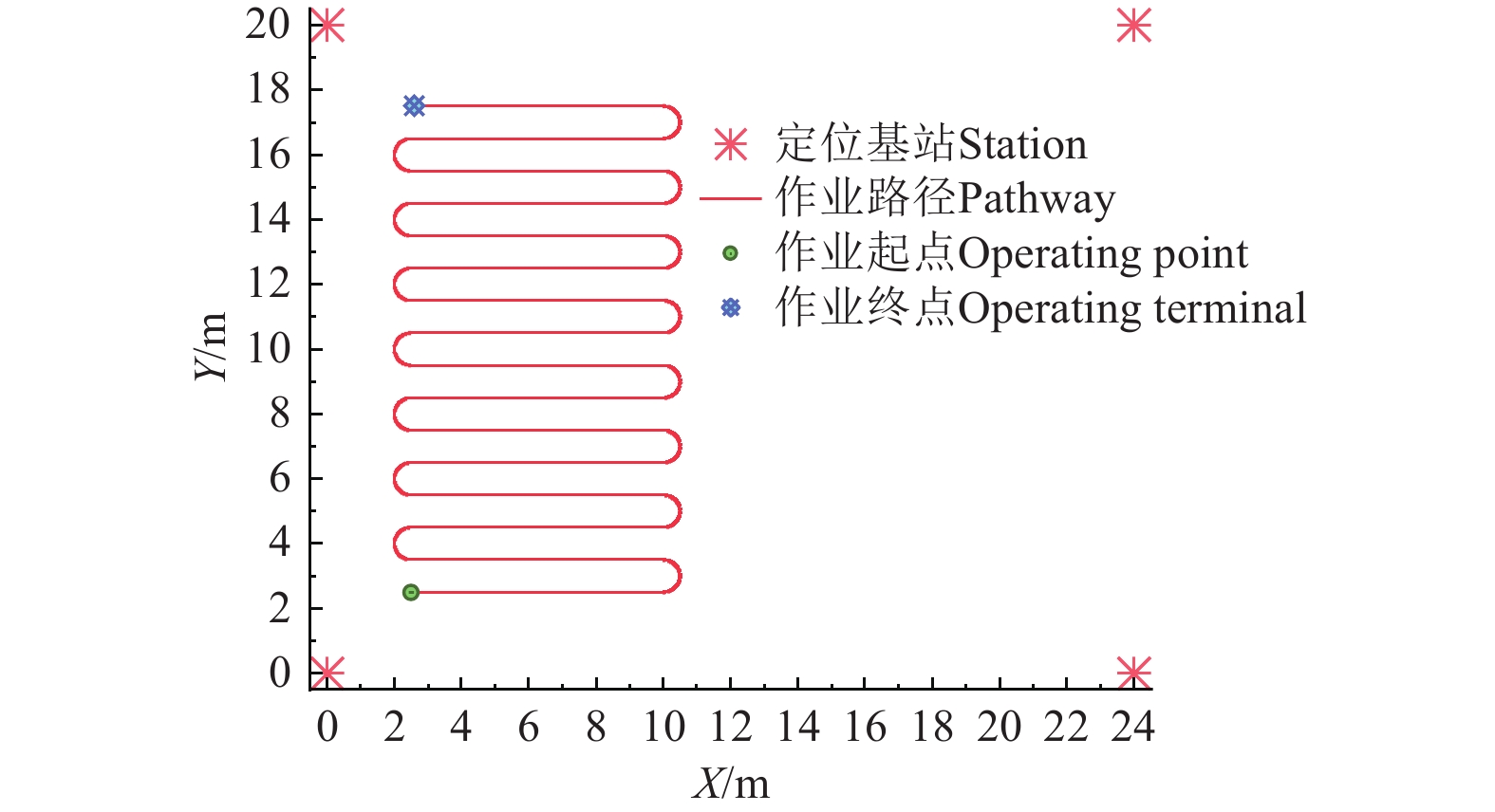
为验证所提组合定位方法的有效性,基于Matlab搭建仿真试验环境。依据移动平台运行参数和传感器特点,主要仿真参数设置如下:移动平台初始坐标为(2.5,2.5,1.5),初始速度为0.2 m/s,速度变化范围为0.1~0.3 m/s,加速度计零偏误差为0.05 m/s2,陀螺仪零偏误差为5 °/h。以设施园艺内常见的四基站布设方式为例,在24 m x 20 m的多跨大棚范围内,布设4个坐标分别为S1(0,0,2)、S2(0,24,2)、S3(20,0,2)、S4(20,24,2)的UWB基站。移动平台作业幅宽为1 m,在大棚1/2区域内,进行往复式全路径规划作业,作业路线如图5所示。
3.1.1 UWB定位数据模拟
通过最小二乘法求解UWB基站距离方程组获得标签坐标,其中测距值包含均值为0、方差为0.1的高斯噪声表示测量过程中的随机误差。为模拟复杂的设施园艺定位环境,随机制造轻度、中度和重度3种非视距误差表示由不同生长阶段的作物、各种结构障碍物等遮挡引起的测距异常值。
3.1.2 PDOP值仿真
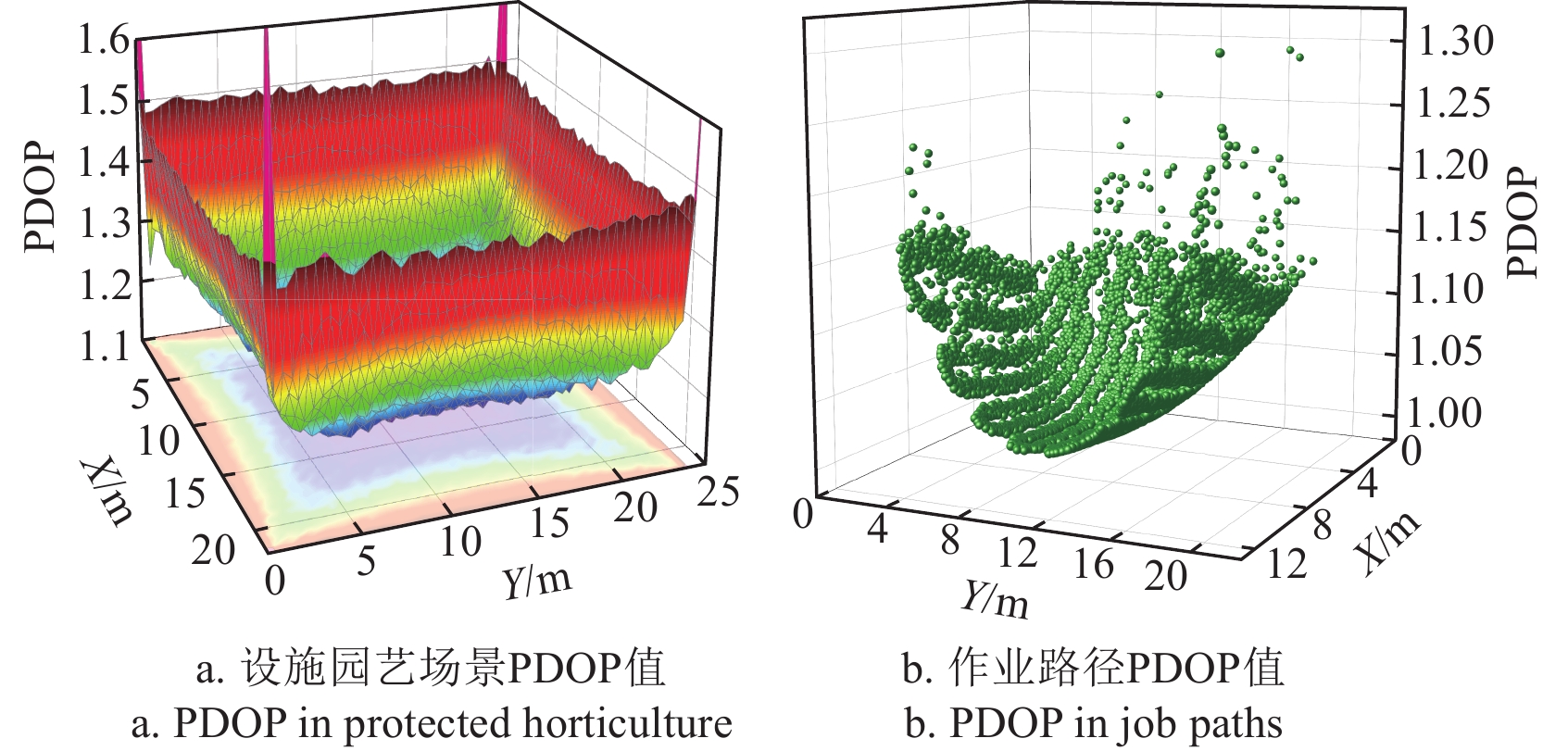
设施园艺场景与作业路径的PDOP值如图6所示。
由图6a可看出,PDOP值关于区域中心基本呈对称分布,在区域中心PDOP值达到最小值1.11,并由中心区域向两边递增。图6b为作业路径上PDOP值变化情况,移动平台是全路径覆盖作业,需要确保整个作业区域的定位精度。当移动平台在大棚中间作业时的PDOP值低于1.20,定位效果较好。当移动平台在靠近仿真区域的边界移动时,PDOP值加速增加,UWB定位系统不稳定。
3.1.3 组合定位效果仿真验证
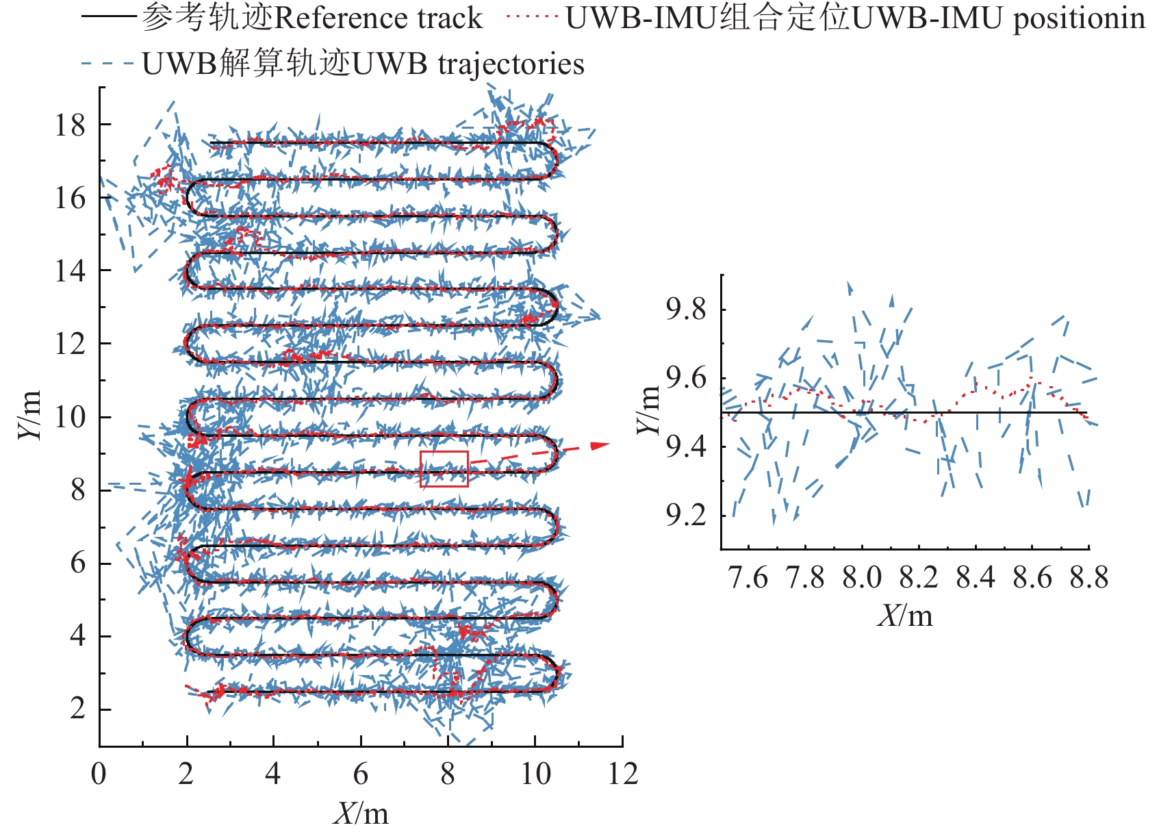
为验证所提UWB-IMU组合定位方法的有效性,对比分析其与单传感器定位的作业轨迹,如图7所示。仿真中IMU采样频率为200 Hz,UWB采样频率为100 Hz。
采用单传感器定位方法的误差为
36.68 cm,最大误差为254.85 cm,波动较大且定位轨迹出现强烈的锯齿效应。而采用UWB-IMU组合定位方法的定位误差为17.53 cm,最大误差为136.68 cm,作业轨迹偏移程度较小,具有良好的定位效果。相比于单传感器定位,采用UWB-IMU组合定位,定位精度提高了52.2%,最大误差降低了46.37%。3.1.4 不同组合定位算法仿真对比
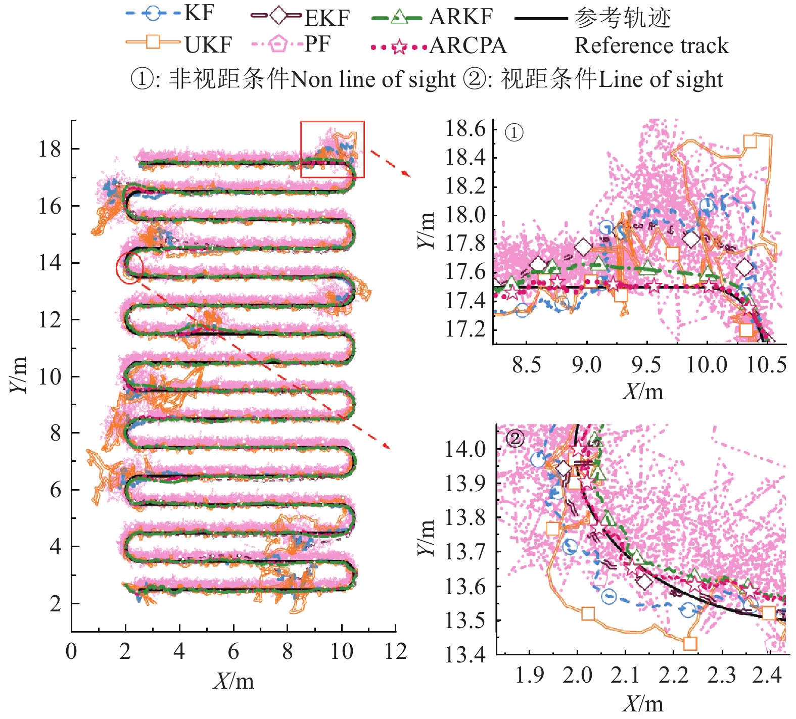
为验证所提组合定位算法的稳健性,分别选用卡尔曼滤波(kalman filtering,KF)、无迹卡尔曼滤波、扩展卡尔曼滤波、粒子滤波(particle filtering,PF)、自适应抗差卡尔曼(adaptive robust kalman filtering,ARKF)等常用滤波定位算法进行比较。图8为6种不同滤波定位算法获得的平面轨迹。
由图8可知,虽然粒子滤波算法具有一定稳定性,但在设施场景下出现明显波动,其主要原因是PF在数据融合过程中过度依赖粒子权重更新,UWB的数据波动使粒子权重变化剧烈,导致定位精度下降。在复杂设施场景中,UKF表现最差,因为UKF对过程噪声和测量噪声的敏感性更高,无法有效滤除NLOS误差和几何误差带来的影响,导致滤波更容易发散。而采用ARCPA算法的定位精度远超其余5种算法,定位结果更稳定,更贴合参考轨迹,在面对NLOS误差时表现出更强的鲁棒性。
图8中局部放大图①为非视距条件下各种算法受NLOS误差影响较大的区域。当出现NLOS误差时,KF、EKF、UKF与PF算法的定位精度均受到较大影响,整体轨迹都出现了严重偏移的现象;ARKF与ARCPA都具有一定的抗差效果,但ARKF随着遮挡时间的增加,定位轨迹逐渐偏离参考路径,且定位误差不断增加,在X轴坐标到达9 m时,Y轴方向误差达到最大为16.09 cm。
图8中的局部放大图②为视距条件下各种算法受几何误差影响较大的区域。该时刻移动平台正处于仿真区域边界,结合图6可知设施园艺场景边界区域PDOP值较高,这表明定位标签与基站之间的锚节点几何分布程度较差,该处UWB定位系统精度较低。从局部放大图②中可以看出KF、EKF和UKF的作业轨迹发生明显偏离,采用ARKF的作业轨迹更接近参考值,但仍无法实现精准定位。而采用所提ARCPA算法的作业轨迹与参考轨迹的重合度最高,这是由于PDOP修正后的抗差因子调节了预测信息和观测信息的占比,提高了设施园艺移动平台在动态和复杂环境中的适应性和鲁棒性。
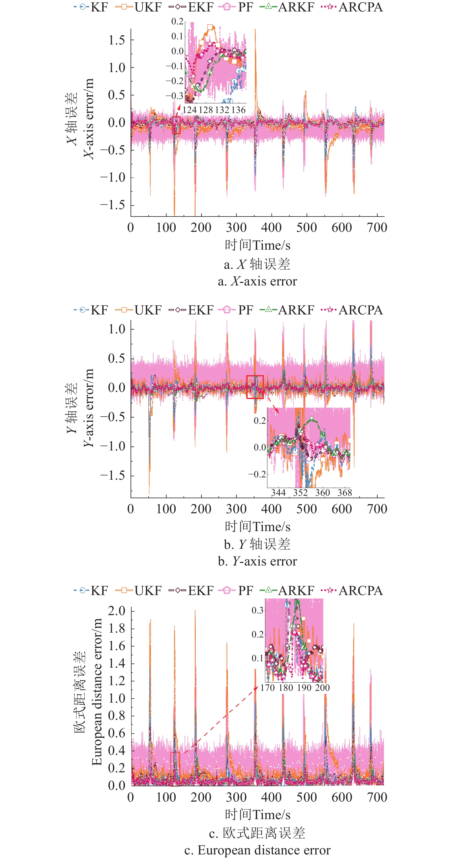
图9统计了6种滤波算法在X、Y轴和欧式距离上的定位误差。由图9a和图9b可知,在视距条件下ARCPA算法定位误差小于10.0 cm。在轻度非视距误差条件下,如图9a中的124~136 s时段,X轴最大定位误差结果仍能保持10.0 cm左右。中度的非视距误差条件下,如图9b中的344~368 s时段,Y轴定位结果仍能保持在20.0 cm以内的偏差。由图9c可知,在重度非视距误差条件下,最大定位误差保持在20.0 cm左右。这表明采用所提ARCPA算法在X轴和Y轴误差明显低于其他5种算法,能有效抑制几何误差和NLOS误差对组合定位系统的干扰。
为充分验证所提定位方法的有效性,统计分析了不同定位方法的误差,如表1所示。相比于单传感器定位,采用所提UWB-IMU组合定位方法并使用ARCPA算法的定位精度提高了81.92%,最大误差降低了88.89%。相比于传统的卡尔曼滤波算法,采用所提ARCPA算法的位置均值误差降低46.89%,均方误差降低86.97%,最大误差降低
1.0836 m,均方根误差降低62.18%。所提ARCPA算法定位精度和稳定性均优于其他5种组合定位算法。表 1 不同定位方法误差统计表Table 1. Error statistics of different positioning methods定位方法
Positioning method位置偏差Positional deviation /cm 均值误差
Mean
error均方误差
Mean squared
error最大误差
Maximum
error均方根误差
Root mean
square error单传感器
Single SensorUWB 23.77 27.94 254.85 36.683 组合定位
Integrated localizationKF 9.79 3.07 136.68 17.53 UKF 18.69 9.22 204.26 30.36 EKF 10.59 2.32 72.76 15.22 PF 24.15 7.86 161.46 28.03 ARKF 5.94 0.65 34.55 8.07 ARCPA 5.20 0.40 28.32 6.63 3.2 实车定位试验
为验证本文所提定位方法在设施场景下的有效性,开展了设施园艺电驱动移动平台(见图10a)定位试验。试验场景为江苏省康博农业科技有限公司的设施园艺基地,如图10b所示。
UWB数据经STM32单片机计算得到测距值,并通过串口进行传输,IMU传感器将采集到的加速度和角速度等运动数据通过RS485通信协议进行传输和解析,通过上位机实时处理并记录UWB和IMU数据。
3.2.1 UWB测距误差标定试验
大棚内的高温高湿环境会对UWB信号传播产生额外误差,特别是高湿环境对UWB波段信号具有吸收作用。此外,UWB内部模块存在的天线延时和算法延时,也会导致UWB信号测量产生偏差。为提高UWB测距精度,以激光测距仪的测距值作为真实值,通过测距试验获得真实距离和UWB测距值之间的映射关系,对视距通信下的UWB误差进行矫正。
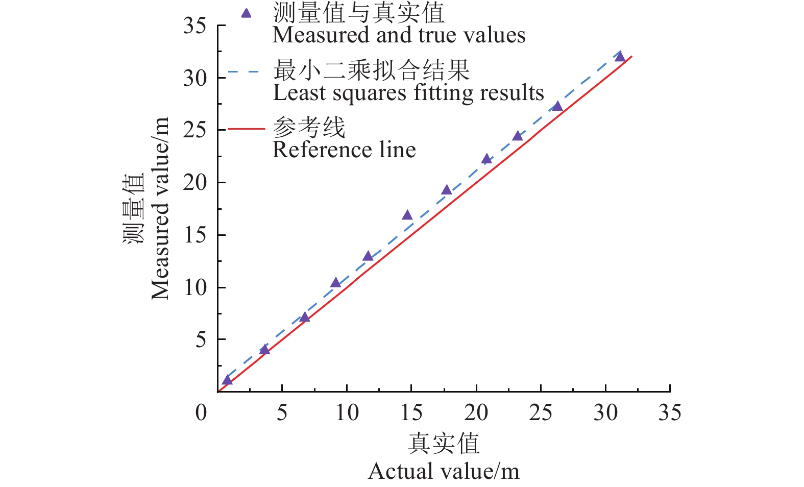
将基站固定于支架上,移动定位标签,每次间隔3 m,分别获取UWB和激光测距仪每个采样位置上的100个测距值,并将原始UWB测距数据和真实值使用最小二乘法进行拟合,结果如图11所示。
经过计算,视距条件下UWB原始测距结果的均方根误差(root mean squared error,RMSE)为1.19 m,修正后的均方根误差为0.49 m。相比于修正前,测距精度提高了58.8%。
3.2.2 动态定位试验
将4个UWB基站安装在大棚区域的四角,其坐标分别为(0,0,1.5)、(0,16,1.5)、(0,24,1.5)和(20,24,1.5)m。将UWB定位标签和IMU分别安装于设施园艺移动平台顶部和底部,移动平台沿着预设的轨迹匀速缓慢行驶,在预设路径上布设若干个检核点用于评价定位精度,利用激光测距仪确定检核点坐标。作业途中由行人、轮胎和金属铁板制造NLOS误差(如图12b所示)。行人身高1.75 m,在检核点27周围移动;轮胎遮挡则通过在检核点18旁1 m处架设直径0.6 m轮胎;金属铁板长1 m、宽0.7 m,固定在检核点23距离0.5 m的梯子上,高度为1.5 m。根据试验结果,行人遮挡引起的误差范围为0.4~0.7 m,轮胎遮挡引起的误差范围为1.0~1.3 m,铁门遮挡引起的误差大于1.7 m,误差统计如表2所示。
表 2 动态定位试验非视距误差统计Table 2. Non line of sight error statistics in dynamic positioning test场景
Scenario遮挡物
Obscuring objects非视距误差
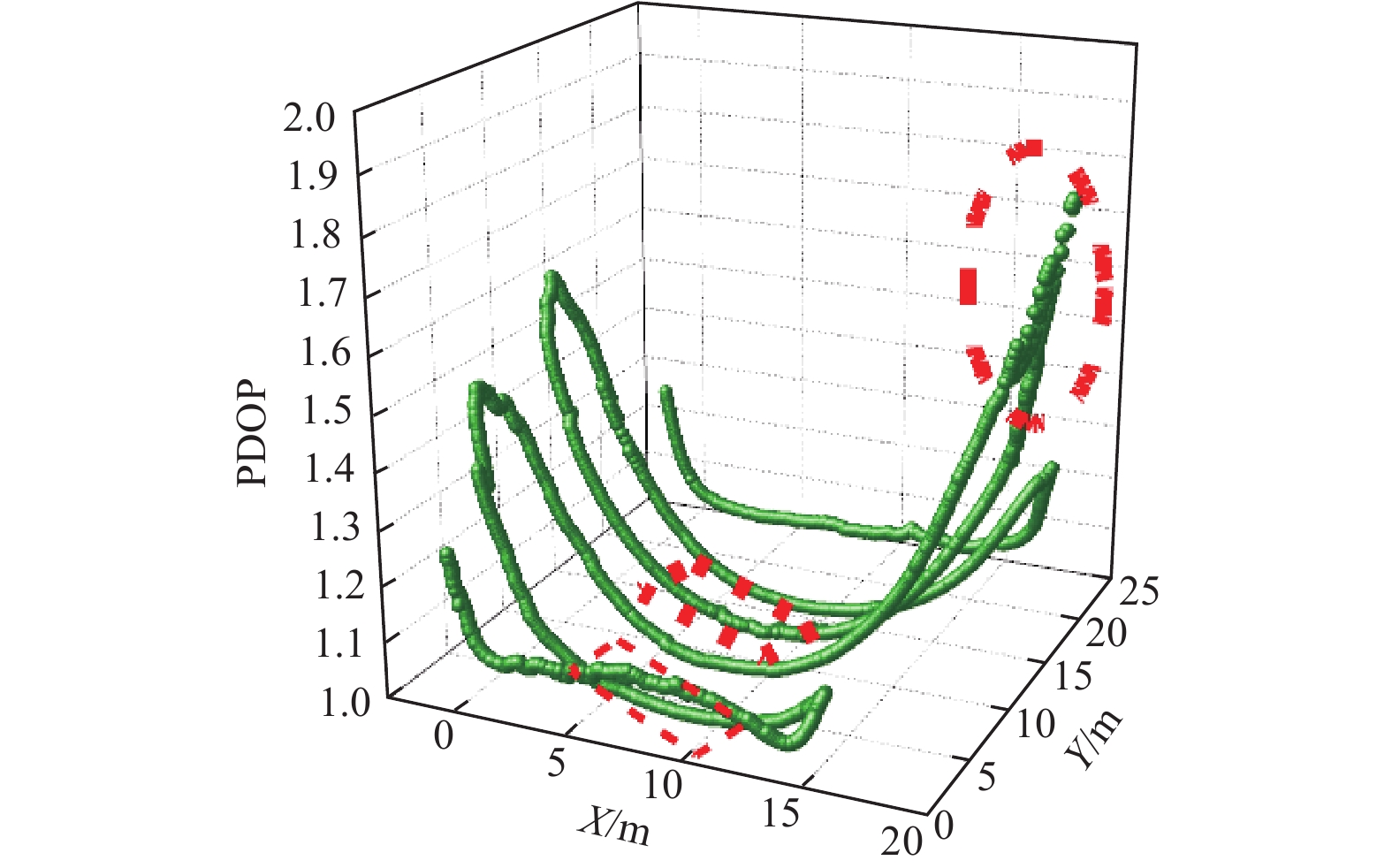
Non line of sight error/m轻度 行人 0.4~0.7 中度 轮胎 1~1.3 重度 金属铁板 ≥1.7 设施园艺移动平台行驶的过程中的PDOP值如图12所示。由图12可知,布设4个基站时PDOP值与仿真结果(图6b)基本相同,这表明中心区域的UWB锚节点分布程度较好。图12中红色区域表示受NLOS误差影响的区域,可以看出PDOP值出现明显波动,此时由于金属铁板对UWB信号的遮挡,造成了严重的NLOS误差,这使得测距数据产生偏差,并直接影响基站几何分布,从而引发PDOP值的波动,表明UWB受到外界干扰导致的定位系统精度下降。
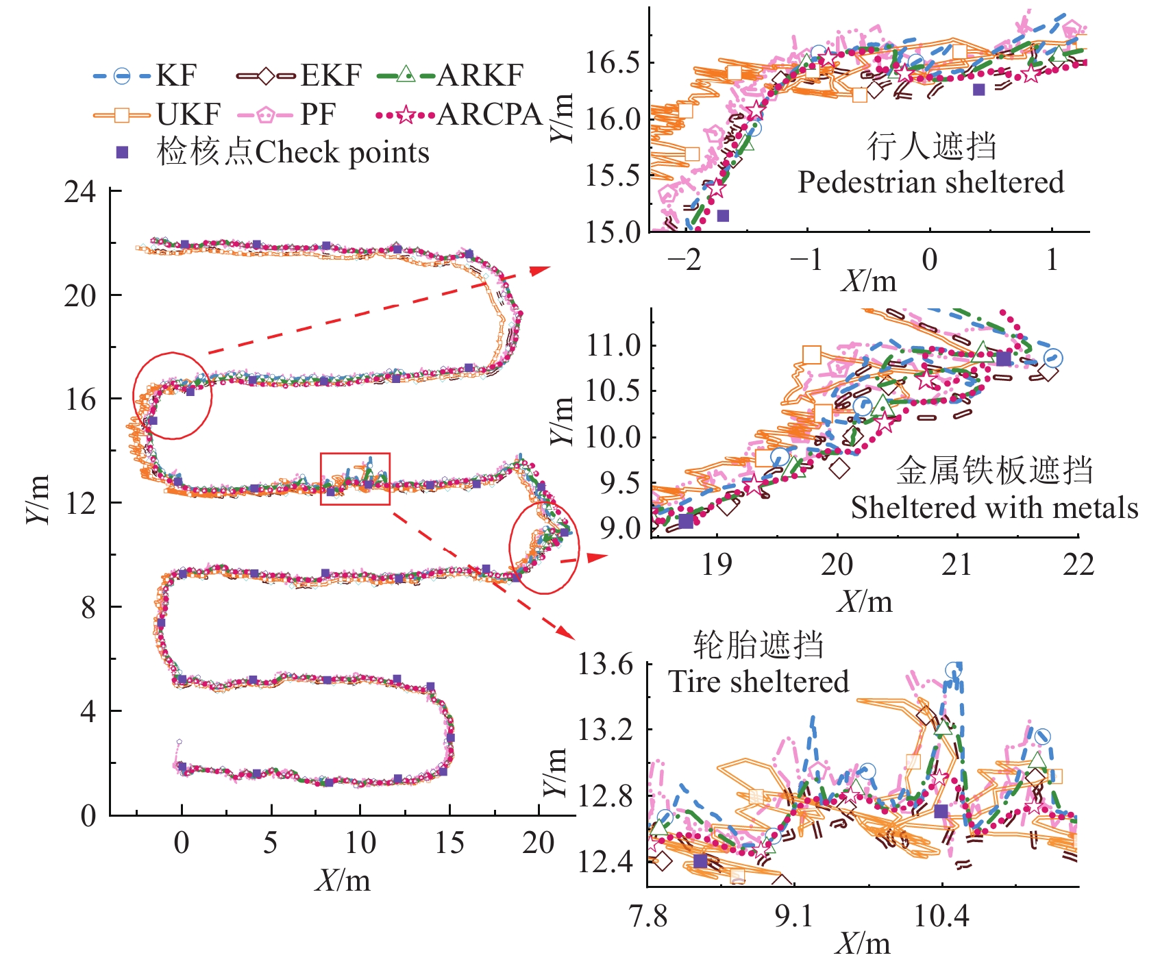
为进一步分析所提ARCPA算法的定位精度,设计不同定位算法对比试验,得到的轨迹和检核点误差分别如图13、图14所示。
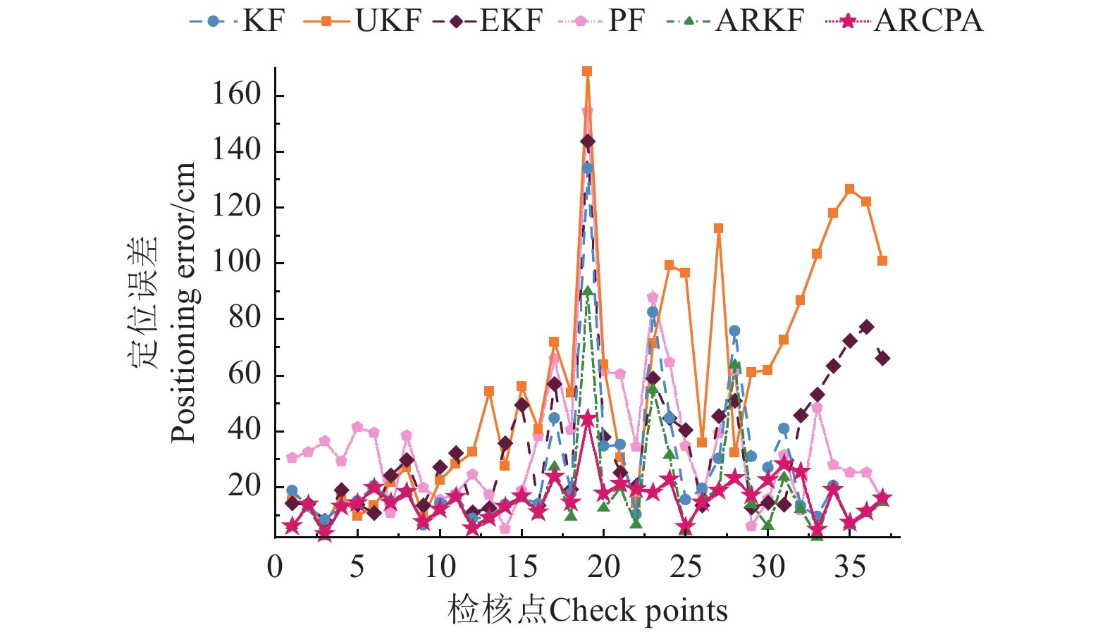
由图13、图14可知,UKF和PF在设施场景下表现出较大的波动和偏离,整体误差较高。EKF和KF存在一定的局限性,特别是在复杂环境和干扰较强的区域,误差峰值高于100.0 cm。相比之下,ARKF和ARCPA算法则表现出更为优越的性能。ARKF在严重几何误差和复杂NLOS场景下,其自适应机制无法完全消除估计误差。总体而言,ARCPA在整个试验过程中均表现出较高的精度和稳定性,且误差基本维持在20.0 cm以下,具有更好的自适应抗差效果。
图13中的行人遮挡区域是受几何误差影响较大的区域,对应图14检核点的26、27、28处。结合图13和图14可知,此时UKF与PF定位数据出现明显波动,定位精度下降;KF、EKF与ARKF具有一定的降噪作用但无法滤除UWB几何误差的干扰,轨迹出现偏离;ARCPA整体误差最小、轨迹更平滑,符合实际定位情况。
图13中的金属铁板遮挡区域和轮胎遮挡区域,分别为重度和中度遮挡区域,对应图14检核点的18、19和23、24处。在受到NLOS误差影响的区域内,各算法的作业轨迹均出现了明显的偏移,UKF和PF算法出现较大的误差波动。在重度遮挡区域,KF、EKF、PF与UKF的最大定位误差分别为
133.96 、143.67 、154.31 和168.78 cm,表现出对复杂环境的适应性不足。虽然ARKF整体误差较低,但作业轨迹存在一定波动,在重度遮挡区域内的最大误差接近100.0 cm,这表明ARKF自适应机制在面对高度几何误差和严重NLOS遮挡叠加时仍存在局限性。相比之下,ARCPA整体误差最低、波动最小,在复杂设施园艺场景下具有高精度和强鲁棒性。表3为动态定位试验的定位精度统计结果。其中,ARCPA的RMSE为
17.70 cm,相比于KF、UKF、EKF、PF、ARKF分别减小了50.15%、74.63%、60.01%、60.88%、28.34%。ARCPA的最大定位误差相较于KF、UKF、EKF、PF、ARKF分别下降了66.83%、73.67%、69.07%、71.2%、50.50%。在复杂的设施园艺定位场景下,ARCPA算法仍能保持较高的稳定性和定位精度。表 3 动态定位试验不同算法最大误差和均方根误差统计Table 3. Statistics of maximum error and root mean square error of different algorithms in dynamic positioning test定位算法
Positioning algorithms位置偏差Positional deviation /cm 最大误差
Maximum error均方根误差
Root-mean-square errorKF 133.96 35.51 UKF 168.78 69.78 EKF 143.67 44.26 PF 154.31 45.25 ARKF 89.77 24.70 ARCPA 44.44 17.70 6种定位算法在不同运算平台的性能对比如表4所示。
表 4 不同算法性能对比Table 4. Performance comparison of different algorithms定位算法Positioning algorithms 运算平台A
Operational platform A
(Intel Core i7-13650HX)运算平台B
Operational platform B
(AMD Ryzen 5 7645HX)平均运行
时间
Average
run time
/ms处理器
使用率
Central processing
unit utilization rate/%平均运行
时间
Average
run time
/ms处理器
使用率
Central processing
unit utilization rate/%KF 72.4 25.2 77.7 33.9 UKF 128.4 58.7 144.7 59.8 EKF 109.6 45.9 119.3 55.7 PF 148.1 50.5 188.5 60.2 ARKF 83.8 40.2 92.9 46.5 ARCPA 96.3 35.6 107.2 50.1 结果显示,ARCPA算法在2种处理器上均具有良好的性能,平均运行时间为96.3和107.2 ms,表明ARCPA算法在计算复杂度和性能需求之间取得了良好的平衡。同时,ARCPA算法的处理器使用率分别为35.6%和50.1%,表明其资源利用的高效性以及运行稳定性,适用于移动平台在设施场景下的实时定位部署。
4. 结 论
为解决设施场景下遮挡严重所致的电驱移动平台定位精度低、稳定性差的问题,本文设计了一种适合设施园艺电驱移动平台的多传感器组合定位方法(UWB/IMU),并提出了一种自适应抗差组合定位算法,为验证所提方法的有效性,搭建了仿真与试验平台,并对应开展了设施园艺电驱移动平台的定位方法对比试验。主要结论如下:
1)所提高精度组合定位方法可显著降低NLOS误差和几何误差对设施园艺电驱移动平台定位精度的影响,单传感器定位精度为
36.68 cm,最大定位误差为254.85 cm,而采用所提UWB/IMU组合定位方法的定位精度提高了81.92%,最大误差降低了88.89%。2)实车定位试验表明,所提组合定位方法即使在复杂设施园艺作业场景下,仍能保持较高的稳健性,相较于常规卡尔曼滤波、无迹卡尔曼滤波、扩展卡尔曼滤波、粒子滤波和抗差自适应卡尔曼滤波,所提定位方法精度分别提升了50.15%、74.63%、60.01%、60.88%、28.34%。
本文所设计的设施园艺电驱移动平台组合定位方法和提出的自适应抗差组合定位算法,能够为设施园艺大棚中作业的移动平台提供稳定且精确的定位的信息,对于提高设施园艺电驱移动平台的作业质量和作业效率具有重要实际生产指导意义。
-
图 2 设施园艺UWB定位系统
注:Ob为载体坐标系,固连于移动平台,按“右前上”顺序定义,Xb沿载体横轴指向载体右侧,Yb沿载体横轴指向载体前方,Zb垂直Xb与Yb所在平面向上。On为导航坐标系,固定于基站S1的地面投影区域,Xn沿大棚横向指向大棚右侧,Yn沿大棚纵向指向大棚前方,Zn垂直Xn与Yn所在平面向上;d1,d2,d3,d4为定位标签到基站S1,S2,S3,S4距离,m。
Figure 2. Protected horticulture UWB positioning system
Note: Ob is the carrier coordinate system, fixed to the mobile platform, defined in the order of “right front up”, with Xb pointing to the right side of the carrier along the transverse axis of the carrier, Yb pointing to the front of the carrier along the transverse axis of the carrier, and Zb perpendicularly upward in the plane where Xb and Yb are located. On is the navigation coordinate system fixed to the projection area of the base station S1 on the ground, Xn points to the right side of the shed along the transverse axis of the shed, Yn points to the front side of the shed along the longitudinal axis of the shed, and Zn is perpendicular to the plane upward where Xn and Yn are located; d1, d2, d3, and d4 denote the distances of the positioning tags to the base station S1, S2, S3, S4, m.
图 4 IMU定位解算原理
注:λ和L分别表示经度和纬度,(°);h表示高度,m;φ、θ、γ表示俯仰角、航向角、横滚角,rad;VE、VN、VU表示东、北、天方向速度分量,m·s-1; \boldsymbol{\boldsymbol{f}}^{\mathit{b}} 和 \boldsymbol{\boldsymbol{f}}^{\mathit{n}} 表示b系和n系下的比力投影,m·s-2; \mathit{\omega}_{ie}^n 表示地球自转角速度矢量在导航坐标系中的投影,rad·s-1; {{{\omega}{_{en}^n}{{{ }}}}{ }} 表示导航坐标系下,地球自转和地球表面运动的角速度,rad·s-1; {\omega_{in}^b} 表示载体坐标系下,导航坐标系相对惯性坐标系的角速度,rad·s-1; \omega_{nb}^b 表示载体坐标系下,导航坐标系相对载体的角速度,rad·s-1; \omega_{in}^n 表示导航坐标系下,载体坐标系相对于惯性坐标系的角速度,rad·s-1。
Figure 4. IMU (inertial measurement unit) positioning calculation principle
Note: λ, L represent longitude, latitude, respectively, (°); h represent altitude, m; φ,θ,and γ denote the pitch angle, yaw angle, and roll angle, respectively, rad; VE, VN, and VU are the velocity components in east, north, and up directions, respectively, m·s-1; {\boldsymbol{f}}^b and \boldsymbol{f}^n refer to specific force projections in b-frame and the n-frame, respectively, m·s-2; \omega_{ie}^n represents projection of the Earth's rotation angular velocity vector in navigation coordinate system, rad·s-1; \omega_{en}^n denotes angular velocity in navigation coordinate system due to both Earth's rotation and movement on Earth's surface, rad·s-1; \omega_{in}^b indicates angular velocity of navigation coordinate system relative to inertial coordinate system in body coordinate system, rad·s-1; \omega_{nb}^b denotes angular velocity of navigation coordinate system relative to body in body coordinate system, rad·s-1; \omega_{in}^n represents angular velocity of body coordinate system relative to inertial coordinate system in the navigation coordinate system, rad·s-1.
表 1 不同定位方法误差统计表
Table 1 Error statistics of different positioning methods
定位方法
Positioning method位置偏差Positional deviation /cm 均值误差
Mean
error均方误差
Mean squared
error最大误差
Maximum
error均方根误差
Root mean
square error单传感器
Single SensorUWB 23.77 27.94 254.85 36.683 组合定位
Integrated localizationKF 9.79 3.07 136.68 17.53 UKF 18.69 9.22 204.26 30.36 EKF 10.59 2.32 72.76 15.22 PF 24.15 7.86 161.46 28.03 ARKF 5.94 0.65 34.55 8.07 ARCPA 5.20 0.40 28.32 6.63 表 2 动态定位试验非视距误差统计
Table 2 Non line of sight error statistics in dynamic positioning test
场景
Scenario遮挡物
Obscuring objects非视距误差
Non line of sight error/m轻度 行人 0.4~0.7 中度 轮胎 1~1.3 重度 金属铁板 ≥1.7 表 3 动态定位试验不同算法最大误差和均方根误差统计
Table 3 Statistics of maximum error and root mean square error of different algorithms in dynamic positioning test
定位算法
Positioning algorithms位置偏差Positional deviation /cm 最大误差
Maximum error均方根误差
Root-mean-square errorKF 133.96 35.51 UKF 168.78 69.78 EKF 143.67 44.26 PF 154.31 45.25 ARKF 89.77 24.70 ARCPA 44.44 17.70 表 4 不同算法性能对比
Table 4 Performance comparison of different algorithms
定位算法Positioning algorithms 运算平台A
Operational platform A
(Intel Core i7-13650HX)运算平台B
Operational platform B
(AMD Ryzen 5 7645HX)平均运行
时间
Average
run time
/ms处理器
使用率
Central processing
unit utilization rate/%平均运行
时间
Average
run time
/ms处理器
使用率
Central processing
unit utilization rate/%KF 72.4 25.2 77.7 33.9 UKF 128.4 58.7 144.7 59.8 EKF 109.6 45.9 119.3 55.7 PF 148.1 50.5 188.5 60.2 ARKF 83.8 40.2 92.9 46.5 ARCPA 96.3 35.6 107.2 50.1 -
[1] ZHANG M R, HAN Y T, Li D P, et al. Smart horticulture as an emerging interdisciplinary field combining novel solutions: past development, current challenges, and future perspectives[J]. Horticultural Plant Journal, 2023, 21(2): 212-218.
[2] 付学谦,杨菲菲,周亚中,等. 设施农业能源互联网智能预警理论:评述与展望[J]. 农业工程学报,2021,37(21):24-33. doi: 10.11975/j.issn.1002-6819.2021.21.004 FU Xueqian, YANG Feifei, ZHOU Yazhong, et al. Intelligent early warning theory of the facility agricultural energy internet: Review and prospect[J]. Transactions of the Chinese Society of Agricultural Engineering (Transactions of the CSAE), 2021, 37(21): 24-33. (in Chinese with English abstract) doi: 10.11975/j.issn.1002-6819.2021.21.004
[3] YAO L, HU D, ZHAO C, et al. Wireless positioning and path tracking for a mobile platform in greenhouse[J]. International Journal of Agricultural and Biological Engineering, 2021, 14(1): 216-223. doi: 10.25165/j.ijabe.20211401.5627
[4] JONES M H, BELL J, DREDGE D, et al. Design and testing of a heavy-duty platform for autonomous navigation in kiwifruit orchards[J]. Biosystems Engineering, 2019, 187: 129-146. doi: 10.1016/j.biosystemseng.2019.08.019
[5] REN X, HUANG B, YIN H. A review of the large-scale application of autonomous mobility of agricultural platform[J]. Computers and Electronics in Agriculture, 2023, 206: 107628. doi: 10.1016/j.compag.2023.107628
[6] 钟银,薛梦琦,袁洪良. 智能农机GNSS/INS组合导航系统设计[J]. 农业工程学报,2021,37(9):40-46. doi: 10.11975/j.issn.1002-6819.2021.09.005 ZHONG Yin, XUE Mengqi, YUAN Hongliang. Design of the GNSS/INS integrated navigation system for intelligent agricultural machinery[J]. Transactions of the Chinese Society of Agricultural Engineering (Transactions of the CSAE), 2021, 37(9): 40-46. (in Chinese with English abstract) doi: 10.11975/j.issn.1002-6819.2021.09.005
[7] HUANG Z, SHIIGI T, TSAY L W J, et al. A sound-based positioning system with centimeter accuracy for mobile robots in a greenhouse using frequency shift compensation[J]. Computers and Electronics in Agriculture, 2021, 187: 106235. doi: 10.1016/j.compag.2021.106235
[8] ZHANG W, GONG L, HUANG S H, et al. Factor graph-based high-precision visual positioning for agricultural robots with fiducial markers[J]. Computers and Electronics in Agriculture, 2022, 201: 107295. doi: 10.1016/j.compag.2022.107295
[9] VROEGINDEWEI J, JORISVAN H, ELDERT J, et al. Probabilistic localisation in repetitive environments: Estimating a robot’s position in an aviary poultry house[J]. Computers and Electronics in Agriculture, 2016, 124: 303-317. doi: 10.1016/j.compag.2016.04.019
[10] 姚立健,杨自栋,夏坡坡,等. 基于超宽带无线定位的农业设施内移动平台路径跟踪研究[J]. 农业工程学报,2019,35(2):17-24. doi: 10.11975/j.issn.1002-6819.2019.02.003 YAO Lijian, YANG Zidong, XIA Popo, et al. Path tracking of mobile platform in agricultural facilities based on ultra wideband wireless positioning[J]. Transactions of the Chinese Society of Agricultural Engineering (Transactions of the CSAE), 2019, 35(2): 17-24. (in Chinese with English abstract) doi: 10.11975/j.issn.1002-6819.2019.02.003
[11] 解开婷,张兆国,王法安,等. 基于全质心WLS-HDS-TWR算法的无人驾驶农业机械协同定位算法研究[J]. 农业机械学报,2024,55(7):27-36,110. doi: 10.6041/j.issn.1000-1298.2024.07.003 XIE Kaiting, ZHANG Zhaoguo, WANG Fa'an, et al. Cooperative localization algorithm for full center mass of WLS-HDS-TWR driverless agricultural machines[J]. Transactions of the Chinese Society for Agricultural Machinery, 2024, 55(7): 27-36,110. (in Chinese with English abstract) doi: 10.6041/j.issn.1000-1298.2024.07.003
[12] 陈兆,王玫,周陬,等. 基于多参数融合的超宽带基站布设优化方法[J]. 电子学报,2023,51(10):2855-2865. CHEN Zhao, WANG Mei, ZHOU Zhou, et al. Optimization method for ultra-wideband base station configuration based on multi-parameter fusion[J]. Acta Electronica Sinica, 2023, 51(10): 2855-2865. (in Chinese with English abstract)
[13] LI D, WANG X, CHEN D, et al. A precise ultra-wide band ranging method using pre-corrected strategy and particle swarm optimization algorithm[J]. Measurement, 2022, 194: 110966. doi: 10.1016/j.measurement.2022.110966
[14] CHOWDHURY B D B , KUBOTA C , et al. Automated workflow analysis in vegetable grafting using an Ultra-Wide Band based real-time indoor location tracking system[J]. Computers and Electronics in Agriculture, 2022, 194: 106773.
[15] YU K, WEN K, LI Y, et al. A novel NLOS mitigation algorithm for UWB localization in harsh Indoor environments[J]. IEEE Transactions on Vehicular Technology, 2018: 686-699.
[16] 毕松,张国轩,李志军,等. 基于测距值修正的温室植保机器人定位方法[J]. 农业机械学报,2023,54(8):347-358. doi: 10.6041/j.issn.1000-1298.2023.08.034 BI Song, ZHANG Guoxuan, LI Zhijun, et al. Positioning method of greenhouse plant protection robot based on distance measurement value correction[J]. Transactions of the Chinese Society for Agricultural Machinery, 2023, 54(8): 347-358. (in Chinese with English abstract) doi: 10.6041/j.issn.1000-1298.2023.08.034
[17] 尹康涌,梁伟,杨吉斌,等. 电力作业场景中一种高效的UWB和IMU融合定位算法[J]. 中国电力,2021,54(8):83-90. YIN Kangyong, LIANG Wei, YANG Jibin , et al. An efficient positioning algorithm based on UWB and IMU fusion in electric power operation scenes[J]. Electric Power, 2021, 54(8): 83-90. (in Chinese with English abstract)
[18] 黄卫华,梅宇恒,章政,等. 基于改进SHKF算法的UWB/IMU组合定位方法[J]. 中国惯性技术学报,2024,32(1):34-41. HUANG Weihua, MEI Yuheng, ZHANG Zheng, et al. UWB/IMU combined positioning method based on improved SHKF algorithm[J]. Journal of Chinese Inertial Technology, 2024, 32(1): 34-41. (in Chinese with English abstract)
[19] 杨秀建,皇甫尚昆,颜绍祥. 基于改进UKF的UWB/IMU/里程计融合定位方法[J]. 中国惯性技术学报,2023,31(5):462-471. YANG Xiujian, HUANGFU Shangkun, YAN Shaoxiang, et al. Fusion positioning method with UWB/IMU/odometer based on the improved UKF[J]. Journal of Chinese Inertial Technology, 2023, 31(5): 462-471. (in Chinese with English abstract)
[20] 徐爱功,杜健,隋心,等. 零速修正与完备监测在UWB/MEMS IMU组合中的应用[J]. 测绘科学,2022,47(12):1-7. XU Aigong, DU Jian, SUI Xin, et al. Application of zero velocity update and integrity monitoring in UWB/MEMS IMU combination[J]. Science of Srveuying and Mapping, 2022, 47(12): 1-7. (in Chinese with English abstract)
[21] 姚露,聂晓根,黄汉阳,等. 无迹卡尔曼滤波算法对UWB/IMU组合定位的研究[J/OL]. 机械科学与技术,(2023-06-04)[2024-09-07]. https://link.cnki.net/doi/10.13433/j.cnki.1003-8728.20230271 Yao Lu, Nie Xiaogen, Huang Hanyang, et al. Research on UWB / IMU combined location based on Unscented Kalman filter algorithm[J/OL]. Mechanical Science and Technology for Aerospace Engineering, (2023-06-04) [2024-09-07]. https://link.cnki.net/doi/10.13433/j.cnki. 1003-8728.20230271. (in Chinese with English abstract)
[22] 邱权,胡青含,樊正强,等. 基于自适应系数卡尔曼滤波的农业移动机器人组合定位[J]. 农业机械学报,2022,53(S1):36-43. doi: 10.6041/j.issn.1000-1298.2022.S1.004 QIU Quan, HU Qinhan, FAN Zhengqiang, et al. Adaptive-coefficient kalman filter based combined positioning algorithm for agricultural mobile robots[J]. Transactions of the Chinese Society for Agricultural Machinery, 2022, 53(S1): 36-43. (in Chinese with English abstract) doi: 10.6041/j.issn.1000-1298.2022.S1.004
[23] MA W, FANG X, LIANG L, et al. Research on indoor positioning system algorithm based on UWB technology[J]. Measurement: Sensors, 2024, 33: 101121. doi: 10.1016/j.measen.2024.101121
[24] 袁洪良,杨浚宇,唐睿,等. 基于低成本惯导和运动约束的农机高精度定位系统研究[J]. 农业机械学报,2023,54(7):17-25. doi: 10.6041/j.issn.1000-1298.2023.07.002 YUAN Hongliang, YANG Junyu, TANG Rui, et al. High-precision localization of autonomous agricultural machinery using low-cost IMU and motion constraints[J]. Transactions of the Chinese Society for Agricultural Machinery, 2023, 54(7): 17-25. (in Chinese with English abstract) doi: 10.6041/j.issn.1000-1298.2023.07.002
[25] 王威,宫淑丽,李晓明. 基于IGWO-STCKF的目标跟踪算法[J/OL]. 北京航空航天大学学报,(2024-8-27) [2024-11-20]. https://link.cnki.net/doi.org/10.13700/j.bh.1001-5965.2024.0623. Wang Wei, Gong Shuli, Li Xiaoming. Target tracking algorithm based on IGWO-STCKF[J/OL]. Journal of Beijing University of Aeronautics and Astronautics, (2024-8-27) [2024-11-20]. https://link.cnki.net/doi.org/10.13700/j.bh.1001-5965.2024.0623. (in Cinese with English abstract)
[26] LI S, ZHANG M, JI Y, et al. Agricultural machinery GNSS/IMU-integrated navigation based on fuzzy adaptive finite impulse response Kalman filtering algorithm[J]. Computers and Electronics in Agriculture, 2021, 191: 106524. doi: 10.1016/j.compag.2021.106524
[27] 李得海,吴文坛,马会林,等. 室内测距型基站组网定位性能分析[J/OL]. 武汉大学学报(信息科学版),(2023-06-07)[2024-09-07]. https://link.cnki.net/doi/10.13203/j.whugis20220513 Li Dehai, Wu Wentan, Ma Huilin, et al. Positioning Performance of the Indoor Networks of Range-based Reference Stations[J/OL]. Geomatics and Information Science of Wuhan University, (2023-0607) [2024-09-07]. https://link.cnki.net/doi/10.13203/j.whugis20220513. (in Chinese with English abstract)


 下载:
下载:
