Analysis and experiment of the factors influencing the velocity of branch outlet in subsoiling shovel blade veined inner channel
-
摘要:
针对叶脉状内通道深松铲内部结构的液体流速变化会影响深松铲的自润减阻与改良液层施的效果的问题,该研究采用基于计算流体动力学的仿真分析并结合物理试验,研究了结构参数(内通道孔径、孔间距、孔数)和工作参数(主通道入口流速)对分支出口液体出流速度的影响。首先利用仿真方法开展单因素试验,优选出试验因素的水平范围值,其次开展Box-Behnken试验,以各分支出口液体出流速度最大值为目标值,对叶脉状内通道多分支出口管的结构参数和工作参数进行优化取值,建立各影响因素与分支出口流速之间的二阶回归模型,并对模型进行优化求解,进而得到最优参数组合为:内通道分支出口孔径为6 mm、孔间距为110 mm、孔数为4、主通道入口流速为7 m/s。在此工况下,内通道分支出口平均流速为3.264 m/s。按最优参数组合条件对叶脉状内通道进行设计加工并进行相应的物理试验,试验结果为内通道分支出口平均流速2.971 m/s,与仿真结果的误差为8.97 %。由此,检验了叶脉状内通道结构优化设计的效果,同时为具有自润减阻与改良液层施的深松铲叶脉状内通道结构的优化设计提供一定的理论基础。
Abstract:Deep pine shovel is one of the protective tillage machines for the soda saline-alkali soil in Northeast China. Among them, the subsoiling shovel blade is one of the main working components in the deep pine shovel. The liquid lubrication and drag reduction have been explored in the self-developed deep pine shovel with the structure of leaf vein-like inner channel in the early stage for the saline and alkaline land improvement. This study aims to determine the effect of self-lubrication and drag reduction of deep pine shovel on the application of the modified liquid layer. The modified agent was also utilized for the layering of self-lubrication and drag reduction in the process of liquid flow rate within the leaf vein-like inner channel. The simulation analysis was adopted as the computational fluid dynamics with the physical test. A systematic investigation was then implemented to clarify the influence of structural parameters (inner channel aperture diameter, aperture spacing, and the number of apertures), and working parameters (inlet flow velocity of the main channel) on the liquid outlet velocity of the branch outlet. Firstly, the simulation model was established with the initial and boundary conditions, meshing and irrelevant verification. The single factor test was then carried out, where the structural and working parameters were taken as the test factors. The optimal level range was also achieved after optimization. The initial conditions were set for the simulation: an inner channel branch outlet hole diameter of 6 mm, a hole spacing of 90-110 mm, a number of holes of 4-6, and a main channel inlet flow rate of 5-7 m/s. After that, the Box-Behnken test was designed and then carried out, according to the single-factor simulation test. The target value was taken as the maximum liquid outflow velocity at the outlet of each branch. The structural and working parameters were optimized for the multi branch outlet pipes in the leaf vein shaped inner channel. The analysis of variance (ANOVA) of the test was used to establish the second-order regression equation between the influencing factors and the branch outlet flow rate. The optimal combination of simulation parameters was obtained to optimize and solve the equation. Finally, a field test was also conducted to verify the model. The results show that the better performance of the improved model was achieved for the further prediction analysis of the target mean flow rate. The ANOVA results showed that the influencing factors of the mean flow rate were ranked in the descending order of the main channel inlet flow rate, the number of branch exit holes in the inner channel, the spacing of branch exit holes in the inner channel. The second-order regression equation was optimally solved to take the maximum average flow velocity at the branch outlet as the target value. The optimal combination of parameters was achieved in the inner channel branch outlet hole spacing of 110 mm, the number of holes at the inner channel branch outlet of 4, the inlet flow velocity of the main channel of 7 m/s, and the hole diameter of the inner channel branch outlet of 6mm. Moreover, the average flow velocity at the branch outlet of the inner channel was 3.264 m/s under the optimal conditions. The physical test was then performed on the optimal combination of parameters for the leaf vein-like inner channel. The maximum flow velocity of 2.971 m/s was found in the inner channel branch outlet. There was the average error of 8.97% between the simulation and the physical test. Therefore, the reliability of numerical simulation was verified to examine the optimized design of the leaf-vein-like inner channel structure. The finding can provide the theoretical reference for the coupled deep-pine and chemical improvement using the leaf-vein-like inner channel with the multi-branch outlet pipe structure in soda saline soils.
-
0. 引 言
东北地区苏打盐碱地是中国盐碱地的主要集中区,对盐碱土壤进行改良研究与实践,使之适宜农作物的生长发育,对提高粮食安全具有重要意义[1-2]。针对东北苏打盐碱地特征,课题组设计了一种具有叶脉状内通道的深松铲[3],可以实现自润减阻配合改良液层施,进而达到改良东北地区苏打盐碱土的目的。目前多孔分布管广泛应用于给排水、滴喷灌等领域[4]。为研究其出流特性,国内外众多学者开展了大量分析研究[5]。不同学者针对不同情况下对多孔管内流体分布的计算方程进行推导, RAVIKUMAR等[6]建立了分析方程来确定压力的变化系数,推导出计算流量变化系数的简单解析方程,用于求解数值问题中的流量变异系数;CHELLAM等[7]研究了具有1道和2道可渗透壁的均匀多孔管内不可压缩层流的特性,建立了四阶微分方程并得到了所有壁面雷诺数的解;刘文华等[8]结合水力学分析理论,对坡度、压力水头、孔距、管长4个参数对沿程压力分布的影响规律开展研究;杜涛等[9]建立多孔管出流控制体模型并对达西-韦斯巴赫公式进行完善,得出了多孔管沿程水头损失的计算公式;一些学者通过物理试验方法对多孔管的液体出流进行了相应研究,王亚朦等[10]根据达西-韦斯巴赫公式,结合理论分析与试验的方法,对不同坡度下多孔分布管内流体压力分布规律开展研究;鞠学良等[11]根据微灌毛管水力解析模型,提出了考虑适宜布置形式的均匀坡微灌毛管设计方案以提高灌水均匀度;杨宝中等[12]结合单孔出流试验结果,对多孔管土中出流计算公式进行分析研究,为多孔管地下灌溉提供参考;随着计算流体动力学的发展,数值模拟技术已成为研究单相流和结构优化的重要工具,钱卫忠等[13]使用有限元分析的方法分析多孔管孔径、管长、水压等因素对多孔管出流速度和流量的影响,并得到影响多孔管出流速度及出流量影响显著的因素;王鹏辉[14]提出了基于CFD的“流场分析设计方法”并对喷淋装置几何结构进行了设计优化;韩圆圆[15]通过数值模拟的方法分析了T型三通管内的气液流动特性及相分布规律。
综上,关于多孔管出流速度及出流量的研究多与水利灌溉工程相关,目前未见将其与深松部件结合的相关研究。针对叶脉状内通道的流场分布规律及影响因素不明确的问题,本文拟采用基于计算流体动力学的仿真方法结合物理试验对其进行研究。首先利用仿真的方法,开展单因素试验,优选出影响内通道分支出口流速的因素水平范围值,其次开展Box-Behnken试验,建立各影响因素与分支出口流速之间的二阶回归模型,进而得到最优参数组合。按最优参数组合条件对叶脉状内通道进行设计加工后进行相应的物理试验,得出物理试验值。通过仿真与物理试验结果的对比,检验叶脉状内通道结构优化设计的效果,从而达到对叶脉状内通道优化设计的目的,为利用叶脉状内通道多分支出口管结构在东北地区苏打盐碱地进行深松及化学改良耦合技术提供理论基础。
1. 数值计算模型与计算方法
1.1 数值计算模型
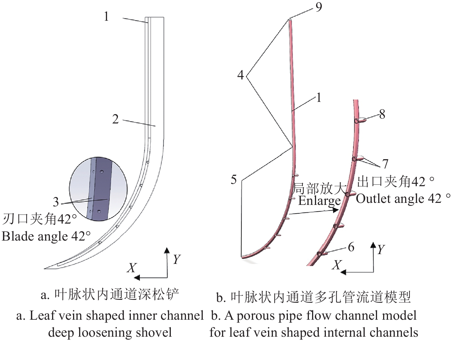
以课题组自研的叶脉状内通道自润滑减阻深松铲的内部结构——叶脉状内通道多分支出口管为研究对象。其深松铲结构由铲柄、弧形铲刃、凿型铲尖及叶脉状多分支出口内通道组成。深松铲铲体长度为1200 mm,其中铲柄长500 mm,弧形铲刃长600 mm,铲尖长100 mm,铲刃横截面为等腰三角形且刃口角度为42°。叶脉状内通道与深松铲铲柄及弧形铲刃的总长度尺寸一致,由主通道直管部分及弧形叶脉状多分支出口管两部分构成,其总长度为1100 mm,主通道直径10 mm,直管部分长度500 mm,弧形叶脉状多分支出口管部分是半径550 mm的圆弧,其长度为600 mm。其中每组分支出口由两个在主通道X轴线上呈42°夹角对称分布的分支出口组成,同时每组分支出口在Y轴上以相同间距在叶脉状内通道多分支出口弧形管段上均匀分布。其叶脉状内通道深松铲及内通道多分支出口管结构如图1。
![]() 图 1 叶脉状内通道深松铲与叶脉状内通道多分支出口管结构图1.主通道 2.深松铲体 3.深松铲刃口夹角42° 4.直管部分 5.弧形管部分 6.末端分支出口 7.分支出口夹角42° 8.首端分支出口 9.主通道入口Figure 1. Structure diagram of deep loosening shovel and a porous pipe flow channel model in leaf vein shaped inner channel1.Main channel 2.Deep loosening shovel body 3. Deep loosening shovel blade angle 42° 4. Straight pipe section 5. Curved tube section 6. End branch outlet 7. Branch outlet angle 42° 8. The head branch outlet 9. Main channel entrance
图 1 叶脉状内通道深松铲与叶脉状内通道多分支出口管结构图1.主通道 2.深松铲体 3.深松铲刃口夹角42° 4.直管部分 5.弧形管部分 6.末端分支出口 7.分支出口夹角42° 8.首端分支出口 9.主通道入口Figure 1. Structure diagram of deep loosening shovel and a porous pipe flow channel model in leaf vein shaped inner channel1.Main channel 2.Deep loosening shovel body 3. Deep loosening shovel blade angle 42° 4. Straight pipe section 5. Curved tube section 6. End branch outlet 7. Branch outlet angle 42° 8. The head branch outlet 9. Main channel entrance1.2 数值模型网格划分
数值模拟计算中选取的叶脉状内通道多孔管的流体计算流域为主通道入口至叶脉状多分支出口处。采用ICEM中的O-Block技术进行流体计算域网格划分[16],可获得较规整的结构网格和较好的边界层网格。计算域采用适应度较强的非结构四面体网格进行划分,算法采用补丁适形法,采用美国机械工程协会(American Society of Mechanical Engineers,ASME)推荐的网格收敛指数 GCI 进行网格离散误差的估计,对网格进行无关性验证[17-19]。最终确定选取中等网格,此时的模型网格总数为198353个,节点总数为43799个,并检查网格问题与质量,结果显示平均网格质量、偏度和纵横比分别为0.837、0.228、1.85, 所生成网格的质量较高,符合本文计算要求。
1.3 数值计算方法及试验设计
1.3.1 数值计算方法
图2为多孔管计算域网格。液体入口位于直管部分顶端,出口位于弧形管部分上的各分支出口上,其余位置均密闭,壁面处设置为无滑移壁面,计算流体使用不可压缩的液态水,进口边界选择流速入口边界条件,对于出口边界条件,采用压力出口边界条件压力值为0,参考压力为标准大气压[20]。采用k-ε湍流模型,依靠计算流体力学求解软件Fluent进行求解[21-24]。在多孔管设置中给定主通道入口流速,经过软件模拟可得到多孔管在该主通道入口流速下达到稳定状态时的内通道各分支出口流速。
1.3.2 试验设计
文章中所讨论的叶脉状内通道分支多孔管,目的是在深松过程中,利用分支出口流出的液体改良剂在铲刃面上形成液膜达到自润滑减阻目的,同时利用流出的改良剂对盐碱地进行化学改良。这就需要每组分支出口的流速要达到一定要求,同时每组分支出口的流量也要达到一定要求,通过大量田间试验发现,叶脉状内通道的结构参数(孔径、孔间距、孔数)及运行参数(主通道入口流速)对分支出口的出流速度及液膜的形成起到决定性作用。因此本文选择分支出口的孔径、孔间距、孔数及主通道入口流速为研究因素。其中孔径即为分支出口的直径,孔间距即为相邻两组分支出口的距离,孔数即为分支出口的组数,主通道入口流速即为改良剂流入主通道的速度。
结合实际工况及多次预试验发现,分支出口6 mm以下的孔径所流出的液体在深松过程中不能够形成将整个深松铲铲面完全覆盖的液膜,即不能保证流量要求,因此选择6 mm以上的孔径进行讨论。分支出口孔间距距离太小及孔数过少则达不到分层减阻及化学改良液层施时所需效果,同时分支出口孔间距距离太大及孔数过多则使最末端分支出口流量太小。在确保各组分支出口的表面积流速大于1 m/s以及所流出的液体能够使铲刃面形成液膜的前提下,初步确定叶脉状内通道分支出口孔径、孔间距、孔数和主通道入口流速4个因素的水平取值范围,进而开展单因素仿真模拟试验,对因素水平进行初步优选,以确定各因素最佳工作水平范围,具体因素水平见表1。研究单因素对各组分支出口流速的影响时,其他因素取中间水平值。
表 1 叶脉状内通道多孔管数值模拟参数Table 1. Numerical simulation parameters of leaf vein shaped inner channel porous tube水平
Factors分支出口孔径
Branch outlet
aperture D/mm分支出口孔间距
Branch outlet
hole spacing
A/mm孔数
Hole number
B主通道入口流速
Main channel
inlet velocity
C/(m·s−1)1 6 80 3 3 2 7 90 4 4 3 8 100 5 5 4 9 110 6 6 5 10 120 7 7 内通道分支出口截面上的最大流速即为表面积最大流速,内通道分支出口截面上的平均流速即为平均流速,两种流速表达的含义不同。距主通道入口最近的一组分支出口即为首端出口,距主通道入口最远的一组分支出口即为末端出口;主通道入口流速在沿程上经过首端或末端分支出口的分流而减少的值即为首端或末端出口分流损失;主通道入口流速在沿程上经过各分支出口的分流而减少的值与主通道入口流速的比值即为流速的分流损失率,以此来量化表征主通道入口流速经过各分支出口被分流的多少,进而分析不同影响因素水平对流速的影响大小。即:首端出口分流损失等于主通道入口流速减去首端分支出口流速;末端出口分流损失等于主通道入口流速减去末端分支出口流速;首末端出口分流损失等于首端分支出口流速减去末端分支出口流速;首端出口分流损失率等于首端出口分流损失与主通道入口流速的比值;末端出口分流损失率等于末端出口分流损失与主通道入口流速的比值;首末端出口分流损失率等于首末端出口分流损失与首端分支出口流速的比值。
2. 结果与分析
2.1 叶脉状内通道多分支出口管沿程流速变化规律
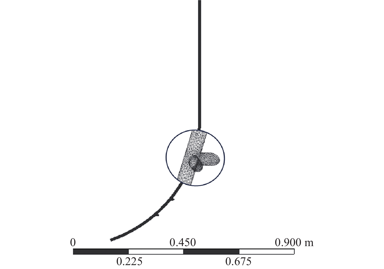
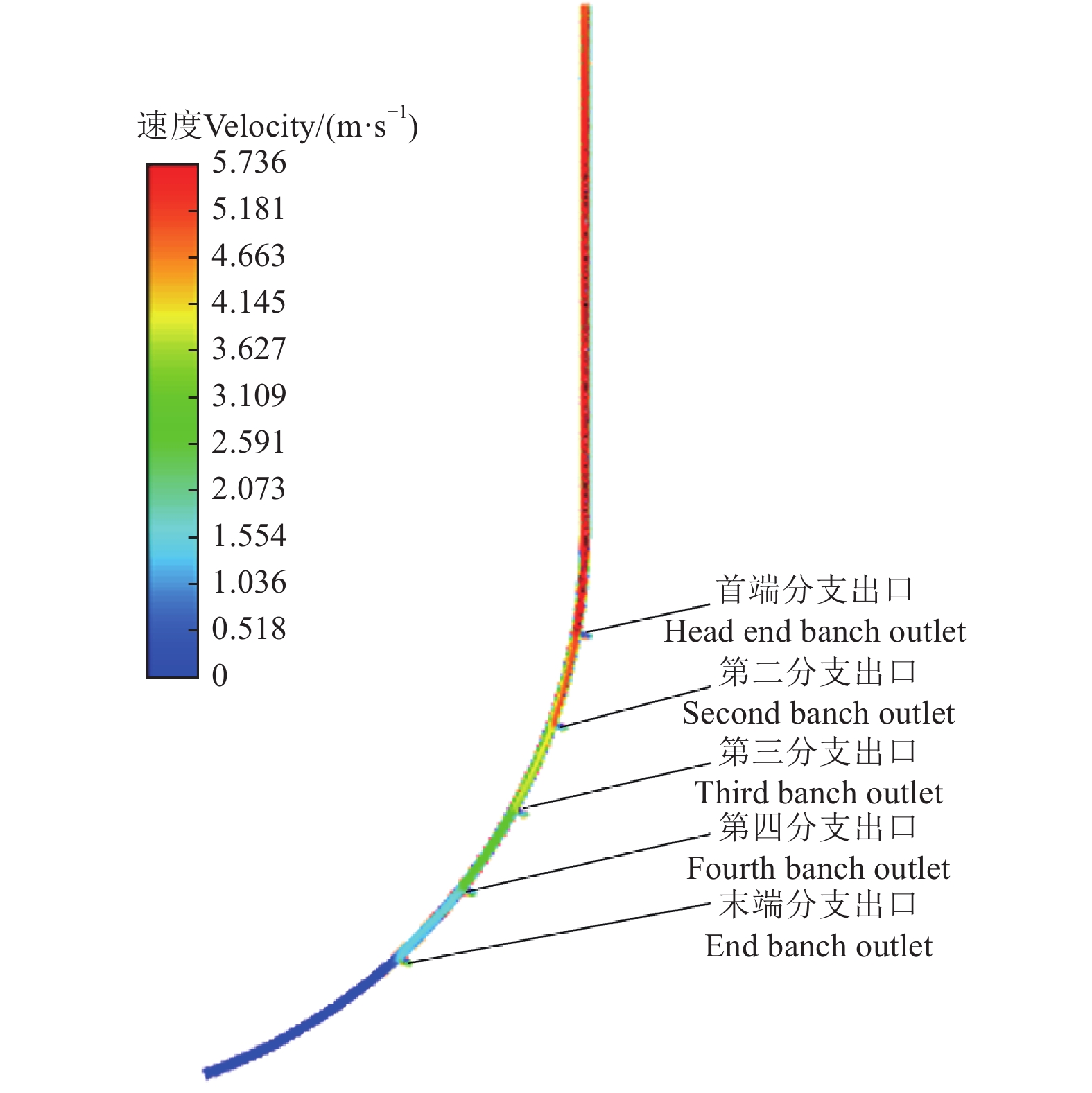
图3为叶脉状内通道主通道流速剖面图。由图3发现叶脉状主通道上沿程流速变化趋势为先逐渐增大后逐渐减小。以叶脉状内通道多分支出口管主通道直径10 mm、内通道分支出口孔径6 mm、孔间距100 mm、孔数5、主通道入口端流速5 m/s时为例,叶脉状主通道上最大流速值为5.736 m/s,最小流速为0。沿程流速从入口处开始逐渐增加直至首组分支出口处上端达到沿程流速最大值,经过首端分支出口下端后开始逐渐减小,在达到末端分支出口后沿程流速逐渐减小至最小值。出现主通道内部沿程流速先逐渐增大后逐渐减小的原因,可能是在射流和惯性重力及离心力的影响作用下,在主通道内部产生沿程流速加速现象,使主通道内部沿程流速先逐渐增大到流速最大值[25];随后液体经过首组内通道分支出口后压力减小,液体开始逐级分流,沿程流速开始逐渐减小。
![]() 图 3 叶脉状内通道主通道流速剖面图Figure 3. Flow velocity profile of main channel in leaf vein shaped inner channel
图 3 叶脉状内通道主通道流速剖面图Figure 3. Flow velocity profile of main channel in leaf vein shaped inner channel2.2 单因素试验结果
通过对初步确定的影响叶脉状内通道分支出口流速的因素进行单因素试验,根据试验数据分析各因素对分支出口流速的影响情况,进一步确定参数范围,试验结果如图4所示。
![]() 图 4 各因素下的内通道分支出口平均流速注:B1为首端分支出口;B2为第二分支出口;B3为第三分支出口;B4为第四分支出口;B6为第六分支出口;B5和B7为末端分支出口。Figure 4. Average flow velocity at the outlet of internal channel branches under various factorsNote:B1is the head branch outlet; B2 is the second branch outlet; B3 is the third branch outlet; B4 is the fourth branch outlet; B6 is the sixth branch outlet; B5 and B7 are the end branch outlet.
图 4 各因素下的内通道分支出口平均流速注:B1为首端分支出口;B2为第二分支出口;B3为第三分支出口;B4为第四分支出口;B6为第六分支出口;B5和B7为末端分支出口。Figure 4. Average flow velocity at the outlet of internal channel branches under various factorsNote:B1is the head branch outlet; B2 is the second branch outlet; B3 is the third branch outlet; B4 is the fourth branch outlet; B6 is the sixth branch outlet; B5 and B7 are the end branch outlet.2.2.1 分支出口孔径对流速的影响
根据图4a可知,随着内通道分支出口孔径的增加,同一分支出口下的流速逐渐减小,同一孔径下的各分支出口流速逐渐减小。当孔径由6 mm增加到10 mm时,表面积最大流速的首端出口分流损失率、末端出口分流损失率及首末端出口分流损失率均逐渐增加,当孔径为6 mm时,表面积最大流速的三种分流损失率分别为4.43%、38.52%和35.67%,均为最小。同时随着孔径的增加内通道分支出口平均流速的首端出口分流损失率、末端出口分流损失率及首末端出口分流损失率同样均逐渐增加,当孔径为6 mm时,平均流速的三种分流损失率分别为67.14%、58.32%和−26.83%,均为最小。孔径由6 mm增加到10 mm时,内通道分支出口表面积最大流速首端出口减小1.567 m/s,末端出口减小1.878 m/s;平均流速首端出口减小0.657 m/s,末端出口减小1.475 m/s。根据结果数据发现在主通道入口流速统一的情况下,内通道分支出口孔径越小,相邻两分支出口的出流速度差值变化越小,随着分支出口孔径的增加,同一孔径下相邻两分支出口出流速度差值逐渐增加,进而使各个分支出口平均流速减小。在孔径为6 mm时液体出流速度最快,因此液体流量也最大,能够达到自润滑减阻的目的。因此优选出叶脉状内通道多孔管模型内通道分支出口孔径为6 mm。
2.2.2 分支出口孔间距对流速的影响
根据图4b可知在内通道分支出口孔间距增加的情况下,内通道分支出口首端出口流速逐渐增大,末端出口流速逐渐减小,这是因为分支出口流速随着孔间距的增加在第二、三分支出口之后降幅开始加剧。同一孔间距下各分支出口流速整体上逐渐减小,只有当孔间距为80 mm时各分支出口流速先增加后减小。当孔间距为80 mm时,首端出口分流损失率同其他孔间距相比最大为26.30%;末端出口分流损失率及首末端出口分流损失率同其他孔间距相比最小,分别为60.22%和46.02%。当孔间距为120 mm时,首端出口分流损失率同比最小为15.46%;末端出口分流损失率及首末端出口分流损失率同其他孔间距相比最大,分别为68.58%和62.83%。同时随着孔间距的增加内通道分支出口平均流速的首端出口分流损失率、末端出口分流损失率及首末端出口分流损失率变化同表面积最大流速变化趋势一样。孔间距由80 mm增加到120 mm时,内通道分支出口表面积最大流速首端出口增加0.542 m/s,末端出口减小0.418 m/s;平均流速首端出口增加0.268 m/s,末端出口减小0.285 m/s。在主通道入口流速统一的情况下,内通道分支出口孔间距越小对各分支出口的首端出口出流速度影响变化较大,反而对末端出口出流速度影响变化较小,当孔间距由90 mm增加到110 mm时流速变化不大,这是叶脉状内通道分支出口这一结构造成的,但在对因素水平讨论优选的过程中是有必要的,因为在实际工作环境中分支出口的位置关系到改良剂液体对深松铲减阻的部位,以及利用叶脉状内通道这一结构进行化学改良过程中,达到化学改良剂分层施用这一目的。因此考虑综合实际试验因素,优选出叶脉状内通道多孔管模型内通道分支出口孔间距90、100、110 mm进行Box-Behnken仿真试验,进一步探究孔间距及其它因素水平交互下对分支出口流速的影响。
2.2.3 分支出口孔数对流速的影响
根据图4c可知在内通道分支出口孔数增加的情况下,内通道分支出口首末端流速均逐渐减小,同一孔数下各分支出口流速整体上是逐渐减小的,只有当孔数为3时各分支出口流速逐渐增加。孔数由3增加到7时,内通道分支出口表面积最大流速的首端出口分流损失率、末端出口分流损失率及首末端出口分流损失率均先增加后减小,当孔数为3时,三种分流损失率均为最小,分别为10.23%、21.49%和12.54%。当孔数为7时,此时首端出口分流损失率不是最大,分别为24.20%、67.44%和57.05%。同时随着孔数的增加内通道分支出口平均流速的首端出口分流损失率、末端出口分流损失率及首末端出口分流损失率变化同表面积最大流速变化趋势一样。孔数由3增加到7时,内通道分支出口表面积最大流速首端出口减少0.698 m/s,末端出口减小2.298 m/s;平均流速首端出口增加0.455 m/s,末端出口减小1.663 m/s。在主通道入口流速统一的情况下,内通道分支出口孔数越少对各分支孔的首末两端组出流速度影响变化越小,通过试验数据可以得出孔数在4~6时对流速影响变化幅度适中,同时为了考虑综合实际试验因素,优选出叶脉状内通道多孔管模型内通道分支出口孔数4、5、6进行Box-Behnken仿真试验,进一步探究孔数对分支出口流速的影响。
2.2.4 主通道入口流速对流速的影响
根据图4 d可知在内通道主通道入口流速增加的情况下,内通道各分支出口的流速是逐渐增大的,同一主通道入口流速下各分支出口流速先增加后逐渐减小。主通道入口流速由3 m/s增加到7 m/s时,内通道分支出口表面积最大流速的首端出口分流损失率逐渐增加,末端出口分流损失率逐渐减少,当主通道入口流速为3 m/s时,首端出口分流损失率同比最小为14.83%;末端出口分流损失率及首末端出口分流损失率同比最大为82.74%和79.74%。当主通道入口流速为7 m/s时,首端出口分流损失率同比最大为26.03%;末端出口分流损失率及首末端出口分流损失率同比最小为54.53%和38.53%。同时随着主通道入口流速的增加内通道分支出口平均流速的首端出口分流损失率先减少后增加,末端出口分流损失率及首末端出口分流损失率均减少。当主通道入口流速为7 m/s时,首端出口分流损失率为78.58%,末端出口分流损失率及首末端出口分流损失率74.38%和−19.58%,均为最小。在其他因素不变的情况下,主通道入口流速为5、6、7 m/s时首端出口分流损失率、末端出口分流损失率及首末端出口分流损失率均为中间值,因此优选出叶脉状内通道多孔管模型内通道分支出口主通道入口流速为5、6、7 m/s进行Box-Behnken仿真试验,进一步探究主通道入口流速对分支出口流速的影响。
3. Box-Behnken仿真试验
基于单因素仿真试验中优选出的各因素范围,设计二次回归正交试验,建立叶脉状内通道分支出口平均流速回归模型,以得到最优参数组合[26]。内通道分支出口孔径在单因素试验中已经优选出最优值为6 mm,其他因素水平如表2所示,Box-Behnken试验设计及结果如表3所示。
表 2 因素水平表Table 2. The factor level table水平
Level分支出口孔间距
Branch outlet
hole spacing
A/mm分支出口孔数
Holes number of branch
outlet B主通道入口流速
Main channel
inlet velocity
C/(m·s−1)−1 90 4 5 0 100 5 6 1 110 6 7 表 3 Box-Behnken试验设计及结果Table 3. Box Behnken experimental design and results序号No. X1 X2 X3 出口流速Outlet velocity/(m·s−1) 1 −1 −1 0 6.069 2 1 −1 0 5.896 3 −1 1 0 5.483 4 1 1 0 5.889 5 −1 0 −1 4.713 6 1 0 −1 4.961 7 −1 0 1 6.456 8 1 0 1 6.806 9 0 −1 −1 4.903 10 0 1 −1 4.769 11 0 −1 1 7.263 12 0 1 1 6.334 13 0 0 0 5.621 14 0 0 0 5.685 15 0 0 0 5.679 16 0 0 0 5.558 17 0 0 0 5.681 注:X1、X2、X3分别为分支出口孔间距、分支出口孔数、主通道入口流速的水平值。 Note: X1, X2, X3 are the levels of branch outlet hole spacing, branch outlet hole number, main channel inlet velocity respectively. Box-Behnken试验方差分析结果如表4所示,由表4的分析结果可知,X2、X3和X2X3对平均流速影响极其显著, X1、X1X2和X 22对平均流速影响显著;X1X3、X12和X32对平均流速影响不显著。模型的P<0.0001,说明回归模型高度显著;模型失拟项P>0.05,说明模型失拟性不显著,回归模型拟合程度高。回归方程决定系数R2=0.9911,校正决定系数R2=0.9796,与1非常接近,且变异系数CV=1.75%。根据统计学上F值越大、表明该因素对结果的影响越大[27-28],通过F值大小,可以判定各因素对平均流速影响的重要性,试验因素对平均流速影响从大到小为主通道入口流速、内通道分支出口孔数、内通道分支出口孔间距;综上表示该回归模型极其显著,能够可靠和真实的反映真实情况,可用于进一步的目标平均流速的预测分析。
表 4 Box-Behnken试验方差分析Table 4. Variance analysis of Box Behnken experiment方差源
Variance
source均方
Mean
square自由度
Degree of
freedom平方和
Sum of
squareF值
F-valueP值
P-value模型Model 7.830 9 0.870 86.21 <0.0001** X1 0.086 1 0.086 8.55 0.0222* X2 0.343 1 0.343 33.96 0.0006** X3 7.060 1 7.060 698.99 <0.0001** X1X2 0.084 1 0.084 8.30 0.0236* X1X3 0.003 1 0.003 0.26 0.6273 X2X3 0.158 1 0.158 15.65 0.0055** X1² 0.012 1 0.012 1.18 0.3141 X2² 0.078 1 0.078 7.75 0.0271* X3² 0.006 1 0.006 0.54 0.4849 残差
Residual0.071 7 0.010 失拟项
Lack of fit0.059 3 0.020 6.39 0.0525 纯误差
Pure error0.012 4 0.003 总和Sum 7.900 16 注: **表明影响极显著(P<0.01),*表明影响显著(P<0.05)。 Note: ** indicates that the impact is extremely significant (P<0.01), and * indicates that the impact is significant (P<0.05). 通过Design–Expert 11.0对Box-Behnken试验结果进行多元回归拟合,得到仿真试验出口流速二阶回归方程:
V=5.64+0.104X1−0.207X2+0.939X3+0.145X1X2+0.026X1X3−0.199X2X3+0.053X21+0.136X22+0.036X23 (1) 在Design–Expert 11.0软件的优化模块中,以分支出口平均流速最大值为优化目标值,将二阶回归方程式(1)中的不显著项剔除后进行优化求解,求解出最优参数组合为内通道分支出口孔间距110 mm、内通道分支出口孔数4、主通道入口流速7 m/s。
为验证仿真优化参数的可靠性,在最优参数条件下进行3次Fluent仿真模拟,得到分支出口平均流速为3.262、3.255、3.275 m/s,其平均值为3.264 m/s。
4. 试验验证
根据数值模拟选定的最优参数组合,加工出用于验证试验的叶脉状内通道多孔管,主通道入口端通过软管、阀门、流量计、变径接头与增压泵相连接构成试验通路,各分支出口由软管及量杯进行承接构成泄放通路,主通道入口流速通过控制流量计算获得,液体流动示意图及实际装置见图5。
![]() 图 5 叶脉状内通道多分支出口流动示意图及试验装置图1.叶脉状内通道深松铲 2.深松铲卡钳 3.流量计 4.变径接头 5.水箱 6.机架 7.软管 8.量杯 9.分支出口Figure 5. Schematic diagram and experimental setup diagram of multi branch outlet flow in leaf vein like internal channels1.Vein shaped inner channel deep loosening shovel 2. Deep loosening shovel caliper 3. Flowmeter 4. Reducer union 5. Water tank 6. Frame 7. Hose 8. Counting cup 9. Branch outlet
图 5 叶脉状内通道多分支出口流动示意图及试验装置图1.叶脉状内通道深松铲 2.深松铲卡钳 3.流量计 4.变径接头 5.水箱 6.机架 7.软管 8.量杯 9.分支出口Figure 5. Schematic diagram and experimental setup diagram of multi branch outlet flow in leaf vein like internal channels1.Vein shaped inner channel deep loosening shovel 2. Deep loosening shovel caliper 3. Flowmeter 4. Reducer union 5. Water tank 6. Frame 7. Hose 8. Counting cup 9. Branch outlet因无法直接测定各分支出口流速,利用图5中量杯,通过软管与深松铲分支出口进行密闭连接,当深松铲达到稳定工作水平状态时,测量出单位时间内各个分支出口所流出液体量Q,根据液体流量计算式(2)计算各分支出口的平均流速[29-31]。
Q=SV (2) 式中Q为分支出口流量,L/min;S为分支出口面积,cm2;V为分支出口平均流速,m/s。
在最优参数组合下,经过3次重复物理试验计算出内通道分支出口平均流速值为2.988、3.102、2.824 m/s,其平均值为2.971 m/s。与仿真值平均误差为8.97%,验证了数值模拟的可靠性,同时检验了叶脉状内通道结构优化设计的效果。分析各分支出口的平均流速小于数值模拟,造成该数据异常的原因可能是实际多分支开孔处不平整,增加了叶脉状内通道多分支出口处的压力损失;另外,实际管路开孔直径的精度有限,而分支孔管出流量对孔径的变化较为敏感,孔径的变化都会对管的流量造成一定的影响。
5. 结 论
1)通过数值仿真分析得到叶脉状内通道多孔管主通道上的沿程流速变化规律为先增大后减小。沿程流速从入口处开始逐渐增加直至首端分支出口处上端达到沿程流速最大值,经过首端分支出口下端后开始逐渐减小,在达到最末组出口端后沿程流速逐渐减小至最小值。
2)采用单因素仿真分析对4个因素进行初步优选,以流速最大为前提,优选出内通道分支出口孔径为6 mm、孔间距为90、100、110 mm、孔数为4、5、6、主通道入口流速为5、6、7 m/s。
3)利用Design–Expert 11.0对仿真数据进行分析,求解得到最优参数组合为内通道分支出口孔间距为110 mm、孔数为4、主通道入口流速为7 m/s。对流速影响因素大小依次为主通道入口流速、内通道分支出口孔数、内通道分支出口孔间距。
4)在最优参数组合下进行仿真与物理试验,内通道分支出口平均流速分别为3.264 m/s和2.971 m/s,误差为8.97%。
-
![]()
图 1 叶脉状内通道深松铲与叶脉状内通道多分支出口管结构图
1.主通道 2.深松铲体 3.深松铲刃口夹角42° 4.直管部分 5.弧形管部分 6.末端分支出口 7.分支出口夹角42° 8.首端分支出口 9.主通道入口
Figure 1. Structure diagram of deep loosening shovel and a porous pipe flow channel model in leaf vein shaped inner channel
1.Main channel 2.Deep loosening shovel body 3. Deep loosening shovel blade angle 42° 4. Straight pipe section 5. Curved tube section 6. End branch outlet 7. Branch outlet angle 42° 8. The head branch outlet 9. Main channel entrance
![]()
图 3 叶脉状内通道主通道流速剖面图
Figure 3. Flow velocity profile of main channel in leaf vein shaped inner channel
![]()
图 4 各因素下的内通道分支出口平均流速
注:B1为首端分支出口;B2为第二分支出口;B3为第三分支出口;B4为第四分支出口;B6为第六分支出口;B5和B7为末端分支出口。
Figure 4. Average flow velocity at the outlet of internal channel branches under various factors
Note:B1is the head branch outlet; B2 is the second branch outlet; B3 is the third branch outlet; B4 is the fourth branch outlet; B6 is the sixth branch outlet; B5 and B7 are the end branch outlet.
![]()
图 5 叶脉状内通道多分支出口流动示意图及试验装置图
1.叶脉状内通道深松铲 2.深松铲卡钳 3.流量计 4.变径接头 5.水箱 6.机架 7.软管 8.量杯 9.分支出口
Figure 5. Schematic diagram and experimental setup diagram of multi branch outlet flow in leaf vein like internal channels
1.Vein shaped inner channel deep loosening shovel 2. Deep loosening shovel caliper 3. Flowmeter 4. Reducer union 5. Water tank 6. Frame 7. Hose 8. Counting cup 9. Branch outlet
表 1 叶脉状内通道多孔管数值模拟参数
Table 1 Numerical simulation parameters of leaf vein shaped inner channel porous tube
水平
Factors分支出口孔径
Branch outlet
aperture D/mm分支出口孔间距
Branch outlet
hole spacing
A/mm孔数
Hole number
B主通道入口流速
Main channel
inlet velocity
C/(m·s−1)1 6 80 3 3 2 7 90 4 4 3 8 100 5 5 4 9 110 6 6 5 10 120 7 7  下载: 导出CSV
表 2 因素水平表
Table 2 The factor level table
水平
Level分支出口孔间距
Branch outlet
hole spacing
A/mm分支出口孔数
Holes number of branch
outlet B主通道入口流速
Main channel
inlet velocity
C/(m·s−1)−1 90 4 5 0 100 5 6 1 110 6 7
下载: 导出CSV
表 3 Box-Behnken试验设计及结果
Table 3 Box Behnken experimental design and results
序号No. X1 X2 X3 出口流速Outlet velocity/(m·s−1) 1 −1 −1 0 6.069 2 1 −1 0 5.896 3 −1 1 0 5.483 4 1 1 0 5.889 5 −1 0 −1 4.713 6 1 0 −1 4.961 7 −1 0 1 6.456 8 1 0 1 6.806 9 0 −1 −1 4.903 10 0 1 −1 4.769 11 0 −1 1 7.263 12 0 1 1 6.334 13 0 0 0 5.621 14 0 0 0 5.685 15 0 0 0 5.679 16 0 0 0 5.558 17 0 0 0 5.681 注:X1、X2、X3分别为分支出口孔间距、分支出口孔数、主通道入口流速的水平值。 Note: X1, X2, X3 are the levels of branch outlet hole spacing, branch outlet hole number, main channel inlet velocity respectively.
下载: 导出CSV
表 4 Box-Behnken试验方差分析
Table 4 Variance analysis of Box Behnken experiment
方差源
Variance
source均方
Mean
square自由度
Degree of
freedom平方和
Sum of
squareF值
F-valueP值
P-value模型Model 7.830 9 0.870 86.21 <0.0001** X1 0.086 1 0.086 8.55 0.0222* X2 0.343 1 0.343 33.96 0.0006** X3 7.060 1 7.060 698.99 <0.0001** X1X2 0.084 1 0.084 8.30 0.0236* X1X3 0.003 1 0.003 0.26 0.6273 X2X3 0.158 1 0.158 15.65 0.0055** X1² 0.012 1 0.012 1.18 0.3141 X2² 0.078 1 0.078 7.75 0.0271* X3² 0.006 1 0.006 0.54 0.4849 残差
Residual0.071 7 0.010 失拟项
Lack of fit0.059 3 0.020 6.39 0.0525 纯误差
Pure error0.012 4 0.003 总和Sum 7.900 16 注: **表明影响极显著(P<0.01),*表明影响显著(P<0.05)。 Note: ** indicates that the impact is extremely significant (P<0.01), and * indicates that the impact is significant (P<0.05).
下载: 导出CSV
-
[1] 张建峰. 盐碱地生态修复原理与技术[M]. 北京:中国林业出版社,2007.12. [2] 商振芳. 我国盐碱地现状及其改良技术研究进展[C]. 2019中国环境科学学会科学技术年会论文集. 西安:2019:386-395. [3] 王景立,荆海洋,郭颖杰,等. 一种具有叶脉状内通道的液体润滑减阻深松机具[P]. 吉林省:CN218244285U,2023-01-10. [4] 符崇梅,魏野畴,李娟,等. 不同灌溉量、滴灌频率及水肥耦合对洋葱产量和水分利用率的影响[J]. 节水灌溉,2011(8):36-39,42. FU Chongmei, WEI Yechou, LI Juan, et al. Influence ofdifferent drip irrigation water amount & frequency and water fertilizer coupling on onion yield and water use efficiency[J]. Water Saving Irrigation, 2011(8): 36-39,42. (in Chinese with English abstract)
[5] 谢淑华,刘焕芳,黄海涛,等. 土工织物反滤层对多孔管汇流量影响的试验研究[J]. 排灌机械工程学报,2022,40(6):576-581. XIE Shuhua, LIU Huanfang, HUANG Haitao, et al. Experimental study on effect of geotextile filter layer on flow of perforated pipe[J]. Journal of Drainage and Irrigation Machinery Engineering, 2022, 40(6): 576-581. (in Chinese with English abstract)
[6] RAVIKUMAR V, RANGANATHAN C R, BOSU S S. Analytical equation for variation of discharge in drip irrigation laterals[J]. Journal of Irrigation and Drainage Engineering, 2003, 129(4): 295-298. doi: 10.1061/(ASCE)0733-9437(2003)129:4(295)
[7] CHELLAM S, LIU M. Effect of slip on existence, uniqueness, and behavior of similarity solutions for steady incompressible laminar flow in porous tubes and channels[J]. Physics of Fluids, 2006, 18(8): 083601-083610.
[8] 刘文华,刘焕芳,黄兴国,等. 多孔管的压力分布特性试验[J]. 水利水电科技进展,2009,29(5):13-15, 88. LIU Wenhua, LIU Huanfang, HUANG Xingguo, et al. Experiment on the pressure distribution characteristic of porous pipe[J]. Advances in Science and Technology of Water Resources, 2009, 29(5): 13-15, 88. (in Chinese with English abstract)
[9] 杜涛,刘焕芳,金瑾, 等. 沿程出流多孔流体分布管压力分布特性[J]. 化学工程,2014,42(9):48-52. DU Tao, LIU Huanfang, JIN Jin, et al. Pressure distribution characteristics of perforated pipe outflowalong pipeline[J]. Chemical Engineering, 2014, 42(9): 48-52. ( in Chinese with English abstract)
[10] 王亚朦,刘焕芳,杜涛,等. 坡度对多孔管压力分布的影响研究[J]. 中国农村水利水电,2017(417):14-17. WANG Yameng, LIU Huanfang, DU Tao, et al. An analysis of the influence of slopes on the pressure head distribution of porous tubes[J]. China Rural Water And Hydropower, 2017(417): 14-17. (in Chinese with English abstract)
[11] 鞠学良,吴普特,Weckler R Paul,等. 均匀坡微灌毛管适宜布置形式优选[J]. 农业机械学报,2016,47(5):123-128. JU Xueliang, WU Pute, Weckler R Paul, et al. Appropriate layouts of micro-irrigation laterals laid on uniformly sloping ground[J]. Transactions of the Chinese Society for Agricultural Machinery, 2016, 47(5): 123-128. (inChinese with English abstract)
[12] 杨宝中,王鹏举,黎明. 多孔管地下灌溉孔口出流分析研究[J]. 安徽农业科学,2010,38(26):14789-14790. YANG Baozhong, WANG Pengju, LI Ming. Analysis and research of the orifice flowaboutunderground irrigation by porous pipe[J]. Journal of Anhui Agricultural Sciences, 2010, 38(26): 14789-14790. (in Chinese with English abstract)
[13] 钱卫忠,张志刚,袁舟龙,等. 多孔管孔出流速度和流量影响因素数值仿真及试验[J]. 船舶工程,2019,41(9):142-150. QIAN Weizhong, ZHANG Zigang, YUAN Zoulong, et al. Numerical simulation and experimental on the influencing factors of orifice exit velocity and flow rate in porous pipe[J]. Ship Engineering, 2019, 41(9): 142-150. (in Chinese with English abstract)
[14] 王鹏辉. 化工设备流动均布及相关协同效应[D]. 上海:华东理工大学,2019. WANG Penghui. Flow Distribution and Relevant Synergy in Chemical Process Equipments[D]. Shanghai:East China University of Science and Technology, 2019. (in Chinese with English abstract)
[15] 韩圆圆. T型三通侧支管内气液两相流体均布及优化研究[D].济南: 山东大学,2018. HAN Yuanyuan. Study on Two Phase Fluid Distribution and Optimization in the Side Branch Pipe of T-junction[D]. Jinan:Shandong University, 2018. (in Chinese with English abstract)
[16] 翁晓星,陈长卿,王刚,等. 基于CFD-DEM的机采鲜叶管道集叶过程数值模拟研究[J]. 农业机械学报,2022,53(11):424-432. WENG Xiaoxing, CHEN Changqin, WANG Gang, et al. Numerical simulation of leaf gathering process of fresh leaf collecting pipeline based on CFD-DEM[J]. Transactions of the Chinese Society for Agricultural Machinery, 2022, 53(11): 424-432. (in Chinese with English abstract)
[17] 王洋,韩亚文,朱新新,等. 基于CFD的射流自吸泵性能优化与试验[J]. 农业工程学报,2016,32(增刊2):16-21. WANG Yang, HAN Yawen, ZHU Xinxin, et al. Optimization and experiment on performance of flow-ejecting self-priming pump based on CFD[J]. Transactions of the Chinese Society of Agricultural Engineering (Transactions of the CSAE),2016,32(Supp.2): 16-21. (in Chinese with English abstract)
[18] 张韦,孟丽苹,李泽宏,等. 基于EDEM-CFD的柴油机DPF孔道内积碳层堵塞特性研究[J]. 农业工程学报,2022,38(16):51-60. ZHANG Wei, MENG Liping, LI Zehong, et al. Blockage characteristics of soot cake layers in the DPF channel of diesel engine basedon EDEM-CFD[J]. Transactions of the Chinese Society of Agricultural Engineering (Transactions of the CSAE), 2022, 38(16): 51-60. (in Chinese with English abstract)
[19] 李俊烨,苏宁宁,胡敬磊,等. 基于CFD-DEM耦合的磨粒流微小孔加工数值分析与试验[J]. 农业工程学报,2018,34(16):80-88. doi: 10.11975/j.issn.1002-6819.2018.16.011 LI Junye, SU Ningning, HU Jinglei, et al. Numerical analysis and experiment of abrasiveflow machining microhole structure based on CFD-DEM coupling[J]. Transactions of the Chinese Society of AgriculturalEngineering (Transactions of the CSAE), 2018, 34(16): 80-88. (in Chinese with English abstract) doi: 10.11975/j.issn.1002-6819.2018.16.011
[20] 张德胜,周游,赵睿杰,等. 垂直管内固-液两相流全耦合CFD-DEM模型研究[J]. 农业机械学报,2022,53(12):212-222. ZHANG Desheng, ZHOU You, ZHAO Ruijie, et al. Solid-liquidtwo-phase flow based on fully coupled CFD-DEM method in vertical pipe[J]. Transactions of the Chinese Society for Agricultural Machinery, 2022, 53(12): 212-222. (in Chinese with English abstract)
[21] 于勇. FLUENT入门与进阶教程[M]. 北京:北京理工大学出版社,2008. [22] NIE B, WANG H, LI L, et al. Numerical investigation of the flow field inside and outside high-pressure abrasive waterjet nozzle[J]. Procedia Engineering, 2011, 26:48-55.
[23] GAO H T, LIU B B, YAN Y Y,et al. Numerical simulation of bubbles motion in lifting pipe of bubble pump for lithium bromide absorption chillers[J]. Applied Thermal Engineering Design Processes Equipment Economics, 2017.115:1398-1406
[24] 孙帮成,李明高. ANSYS FLUENT 14.0仿真分析与优化设计[M]. 北京:机械工业出版社,2014. [25] 喻黎明,刘凯硕,韩栋,等. 不同工况下Y型网式过滤器流场数值模拟分析[J]. 农业机械学报,2022,53(2):346-354. YU Liming, LIU Kaishuo, HAN Dong, et al. Numerical simulation analysis of flow field of y-screen filter under different working conditions[J]. Transactions of the Chinese Society for Agricultural Machinery, 2022, 53(2): 346-354. (in Chinese with English abstract)
[26] 侯加林,张二鹏,孙宜田,等. 纽扣式压力补偿灌水器结构优化与性能分析[J]. 农业工程学报,2022,38(12):100-108. HOU Jialin, ZHANG Erpeng, SUN Yitian, et al. Structural optimization and performance analysis of button pressure-compensating emitters[J]. Transactions of the ChineseSociety of Agricultural Engineering (Transactions of the CSAE), 2022, 38(12): 100-108. (in Chinese with Englishabstract)
[27] 郝志豪,郑恩来,李勋,等. 免耕播种机旋耕刀耕作性能分析与结构优化[J]. 农业工程学报,2023,39(2):1-13. HAO Zhihao, ZHENG Enlai, LI Xun, et al. Performanceanalysis of the soil-contacting parts for no-tillage planters and optimization of blade structure[J]. Transactions of the Chinese Society of Agricultural Engineering (Transactions of the CSAE), 2023, 39(2): 1-13. (in Chinese with English abstract)
[28] 邓晰文,林贤衍,贾德文,等. 柴油转子发动机的全可变配气系统优化[J]. 农业工程学报,2021,37(4):114-121. DENG Xiwen, LIN Xianyan, JIA Dewen, et al. Optimization of fully variable valve system in a diesel rotary engine[J]. Transactions of the Chinese Society of Agricultural Engineering (Transactions of the CSAE), 2021, 37(4): 114-121. (in Chinese with English abstract)
[29] 高海鹰,马金霞,李贺,等. 水力学[M]. 南京:南京东南大学出版社,202201.242. [30] 方达宪,王艳华,王伟,等. 流体力学[M]. 南京:南京东南大学出版社,201801.258. [31] 张晓元,李长城. 有压管道的流量计算[J]. 节水灌溉,2003(5):16-17, 45. ZHANG Xiaoyuan, LI Changcheng. Flux calculation of pressure pipe[J]. Water Saving Iirrigation, 2003(5): 16-17,45. (in Chinese with English abstract)
-
期刊类型引用(1)
1. 陈继锟,雷基林,刘阳,邹梁楠,莫瑞,张海丰,陈丽琼. 农用柴油机钢活塞销孔-销的摩擦副润滑特性分析. 农业工程学报. 2024(02): 208-216 .  本站查看
本站查看
其他类型引用(1)


计量
- 文章访问数: 184
- HTML全文浏览量: 25
- PDF下载量: 88
- 被引次数: 2